

Kirchhoff’s circuit laws lie at the heart of circuit analysis. With the help of these laws and the equation for individual components (resistor, capacitor and inductor), we have the basic tool to start analyzing circuits. In this article, we will discuss Kirchhoff’s current and voltage law and how to employ them in circuit analysis.
History about Gustav Robert Kirchhoff:-

Gustav Robert Kirchhoff, a German physicist, was born on March 12, 1824, in Konigsberg, Prussia. His first research topic was on the conduction of electricity. This research led to Kirchhoff formulating the Laws of Closed Electric Circuits in 1845. These laws were eventually named after Kirchhoff and are now known as Kirchhoff’s Voltage and Current Laws. Since these laws apply to all electric circuits, understanding their fundamentals is paramount in the understanding of how an electronic circuit functions. Although these laws have immortalised Kirchhoff in the field of Electrical Engineering, he has additional discoveries. He was the first person to verify hat an electrical impulse travelled at the speed of light. Furthermore, Kirchhoff made a major contribution to the study of spectroscopy and he advanced the research into blackbody radiation.
What are Kirchhoff’s Law?
In 1845, a German physicist, Gustav Kirchhoff developed a pair of laws that deal with the conservation of current and energy within electrical circuits. These two laws are commonly known as Kirchhoff’s Voltage and Current Law. These laws help in calculating the electrical resistance of a complex network or impedance in case of AC and the current flow in different streams of the network. In the next section, let us look at what these laws state.
What do Kirchhoff’s laws state?
- Kirchhoff’s Current Law goes by several names as Kirchhoff’s First Law and Kirchhoff’s Junction Rule. According to the Junction rule, in a circuit, the total of the currents in a junction is equal to the sum of currents outside the junction.
- Kirchhoff’s Voltage Law goes by several names as Kirchhoff’s Second Law and Kirchhoff’s Loop Rule. According to the loop rule, the sum of the voltages around the closed loop is equal to null.
Kirchhoff’s First Law
According to Kirchhoff’s Current Law,(KCL)
The total current entering a junction or a node is equal to the charge leaving the node as no charge is lost.
Put differently, the algebraic sum of every current entering and leaving the node has to be null. This property of Kirchhoff law is commonly called as Conservation of charge wherein, I(exit) + I(enter) = 0.

In the above figure, the currents I1, I2 and I3 entering the node is considered positive, likewise, the currents I4 and I5 exiting the nodes is considered negative in values. This can be expressed in the form of an equation:
I1 + I2 + I3 – I4 – I5 = 0
The term Node refers to a junction or a connection of two or more current-carrying routes like cables and other components. Kirchhoff’s current law can also be applied to analyze parallel circuits.
Kirchhoff’s Second Law
According to Kirchhoff’s Voltage Law,(KVL)
The voltage around a loop equals to the sum of every voltage drop in the same loop for any closed network and also equals to zero.
Put differently, the algebraic sum of every voltage in the loop has to be equal to zero and this property of Kirchhoff’s law is called as conservation of energy.

When you begin at any point of the loop and continue in the same direction, note the voltage drops in all the direction either negative or positive and return to the same point. It is essential to maintain the direction either counterclockwise or clockwise; else the final voltage value will not be equal to zero. The voltage law can also be applied in analyzing circuits in series.
When either AC circuits or DC circuits are analyses based on Kirchhoff’s circuit laws, you need to be clear with all the terminologies and definitions that describe the circuit components like paths, nodes, meshes, and loops.
Kirchhoff’s Law Solved Example
If R1 = 2Ω, R2 = 4Ω, R3 = 6Ω, determine the electric current that flows in the circuit below.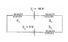
Solution:
- You need to choose the direction of the current. In this problem, let us choose the clockwise direction.
- When the current flows across the resistor, there is a potential decrease. Hence, V = IR is signed negative.
- If the current moves from low to high then the source of emf (E) signed positive because of the charging of energy at the emf source. Likewise, if the current moves from high to low voltage (+ to -) then the source of emf (E) signed negative because of the emptying of energy at the emf source.
In this solution, the direction of the current is the same as the direction of clockwise rotation.
– IR1 + E1 – IR2 – IR3 – E2 = 0
Substituting the values in the equation, we get
–2I + 10 – 4I – 6I – 5 = 0
-12I + 5 = 0
I = -5/-12
I = 0.416 AThe electric current that flows in the circuit is 0.416 A. The electric current is signed positive which means that the direction of the electric current is the same as the direction of clockwise rotation. If the electric current is negative then the direction of the current would be in anti-clockwise direction.
Common DC Circuit Theory Terms:
- Circuit – a circuit is a closed loop conducting path in which an electrical current flows.
- Path – a single line of connecting elements or sources.
- Node – a node is a junction, connection or terminal within a circuit were two or more circuit elements are connected or joined together giving a connection point between two or more branches. A node is indicated by a dot.
- Branch – a branch is a single or group of components such as resistors or a source which are connected between two nodes.
- Loop – a loop is a simple closed path in a circuit in which no circuit element or node is encountered more than once.
- Mesh – a mesh is a single closed loop series path that does not contain any other paths. There are no loops inside a mesh.
Note that:Components are said to be connected together in Series if the same current value flows through all the components.
Components are said to be connected together in Parallel if they have the same voltage applied across them.
A Typical DC Circuit

Kirchhoffs Circuit Law Example No1
Find the current flowing in the 40Ω Resistor, R3

The circuit has 3 branches, 2 nodes (A and B) and 2 independent loops.
Using Kirchhoffs Current Law, KCL the equations are given as:
At node A : I1 + I2 = I3
At node B : I3 = I1 + I2
Using Kirchhoffs Voltage Law, KVL the equations are given as:
Loop 1 is given as : 10 = R1 I1 + R3 I3 = 10I1 + 40I3
Loop 2 is given as : 20 = R2 I2 + R3 I3 = 20I2 + 40I3
Loop 3 is given as : 10 – 20 = 10I1 – 20I2
As I3 is the sum of I1 + I2 we can rewrite the equations as;
Eq. No 1 : 10 = 10I1 + 40(I1 + I2) = 50I1 + 40I2
Eq. No 2 : 20 = 20I2 + 40(I1 + I2) = 40I1 + 60I2
We now have two “Simultaneous Equations” that can be reduced to give us the values of I1 and I2
Substitution of I1 in terms of I2 gives us the value of I1 as -0.143 Amps
Substitution of I2 in terms of I1 gives us the value of I2 as +0.429 Amps
As : I3 = I1 + I2
The current flowing in resistor R3 is given as : -0.143 + 0.429 = 0.286 Amps
and the voltage across the resistor R3 is given as : 0.286 x 40 = 11.44 volts
The negative sign for I1 means that the direction of current flow initially chosen was wrong, but never the less still valid. In fact, the 20v battery is charging the 10v battery.
Application of Kirchhoffs Circuit Laws
These two laws enable the Currents and Voltages in a circuit to be found, ie, the circuit is said to be “Analysed”, and the basic procedure for using Kirchhoff’s Circuit Laws is as follows:
- Assume all voltages and resistances are given. ( If not label them V1, V2,… R1, R2, etc. )
- Assigns a current to each branch or mesh (clockwise or
anticlockwise) - Label each branch with a branch current. ( I1, I2, I3 etc. )
- Find Kirchhoff’s first law equations for each node.
- Find Kirchhoff’s second law equations for each of the independent loops of the circuit.
- Use Linear simultaneous equations as required to find the unknown currents.
As well as using Kirchhoffs Circuit Law to calculate the various voltages and currents circulating around a linear circuit, we can also use loop analysis to calculate the currents in each independent loop which helps to reduce the amount of mathematics required by using just Kirchhoff’s laws. In the next tutorial about DC circuits, we will look at Mesh Current Analysis to do just that.

One thought on “Kirchhoff’s Law”
Comments are closed.