We know that meter is an electronic device used to measure a particular quantity and it is associated with the measurement system. Similarly, the ammeter is nothing but ampere-meter used to measure ampere value. Here ampere is the unit of current and ammeter is used to measure current. There are two kinds of electric current namely AC and DC. AC changes the flow of current direction at regular intervals whereas the DC supplies the current in one direction. This article discusses an overview of what is an ammeter, circuit, types, and applications.
What is an Ammeter?
Definition: A device or instrument that is used to measure the current is called the ammeter. The unit of the current is ampere. So this device measures the current flow in ampere is named as an ammeter or ampere meter. The internal resistance of this device is ‘0’ however in practical; it has some amount of internal resistance. The measuring range of this device mainly depends on the resistance value. The ammeter diagram is shown below.
ammeter
The working principle of an ammeter mainly depends on resistance as well as inductive reactance. This device includes extremely less impedance because it must include less amount of voltage drop across it. It is connected in series because the flow of current within the series circuit is the same.
The main function of this device is to measure the flow of current with the help of a set of coils. These coils have very low resistance & inductive reactance. The ammeter symbolic representation is shown below.
Ammeter Circuit Diagram
The construction of ammeter can be done in two ways like series and shunt. The following circuit represents the basic circuit diagram and the connection of the ammeter circuit in series and parallel are shown below.
series-circuit
Once this device is connected in series in the circuit, then the total measurand current will flow through the meter. So the loss of power occurs within ammeter due to their internal resistance & the measurand current. This circuit includes less resistance so less voltage drop will occur within the circuit.
Here, the resistance of this device is kept small due to the reasons like the total measurand current will flow throughout the ammeter and less voltage drop will occur across the device.
parallel-circuit
When the high current flows through this device, the internal circuit of the device will be damaged. To overcome this problem in the circuit, the shunt resistance can be connected within parallel to the ammeter. If the huge measurand current supplies throughout the circuit, the main current will pass throughout the shunt resistance. This resistance will not have an effect on the function of a device.
Classification/Types of Ammeters
These are classified into different types based on their applications which include the following.
Moving Coil
Electrodynamic
Moving-iron
Hotwire
Digital
Integrating
Moving Coil
This type of ammeter is used to measure both AC & DC. This device uses magnetic deflection where the flow of current through a coil will make to move within the magnetic field. The coil in this device moves freely moves between permanent magnet poles.
Electrodynamic
This type of ammeter includes a moving coil to rotate in the generated field through a fixed coil. The main function of this device is to measure AC & DC with an accuracy of 0.1 to 0.25%. The accuracy of this device is high when compared with the moving coil & permanent magnet moving coil. The device calibration is the same for AC & DC.
Moving-iron
This type of ammeter is used to calculate alternating currents & voltages. In this device, the movable system includes specially created soft iron pieces, which move as acted upon through the electromagnetic force of a fixed coil of wire. These types of devices are classified into two types like repulsion and attraction. This device includes different components like moving element, coil, control, damping & reflective torque.
Hot Wire
This is used to measure AC or DC by transmitting it through a wire to make the wire heated and expand is known as a hot wire. The working principle of this device is to increase the wire by providing heat effect from the current supply through it. This is used for both AC & DC.
Digital Ammeter
This type of device is used to measure the flow of current in amperes & displays the values of on a digital display. The designing of this device can be done by using a shunt resistor to generate a calibrated voltage that is proportional to the flow of current. These instruments provide information regarding the current draw & continuity in order to assist the consumer to troubleshoot variable loads & trends.
Integrating
In this device, the flow of current is summed over time and gives the product of time & current. These devices calculate the whole energy supplied through the circuit in a specified interval of time. The best example of this integrating device is watt-hour meter as it measures the energy directly in watt-hour.
Effect of Temperature in Ammeter
The ammeter is easily influenced by external temperature. So the temperature change will cause a fault in the reading. To overcome this, swamping resistance is used because the temperature co-efficient of this resistance is zero. In the following circuit, the ammeter & the swamping resistance is connected in series so that the effect of temperature on this can be reduced.
effect-of-temperature
This device includes a fuse to protect from external heavy current. If the flow of current through the circuit is high, then the circuit will damage and the ammeter will not measure the flow of current until it is replaced with others. In this way, the temperature effect on this device can be reduced.
Applications
The applications of ammeter include the following.
The applications of this device will range from the schools to industries.
These are used to measure the current flow in the buildings to ensure that the flow is not too low or too high.
It is used in manufacturing and instrumentation companies to check the functionality of the devices
It is used with a thermocouple to check the temperature.
Electricians frequently use these devices to check the faults of the circuits in the building.
FAQs
1). What is the function of an ammeter?
A measuring device used to measure the flow of current within the circuit.
2). Who invented ammeter?
In the year 1884, Friedrich Drexler has invented the first ammeter like moving-iron meter.
3). What is the SI unit for the electric current?
Ampere
4). What is AC Ammeter?
The device used to measure the AC that supplies through an electric circuit is known as AC ammeter.
5). What is the formula for the current?
According to Ohm’s Law Current (I) = Voltage (V)/Resistance (R)
Voltmeter is an electrical measuring instrument used to measure potential difference between two points. The voltage to be measured may be AC or DC. Two types of voltmeters are available for the purpose of voltage measurement i.e. analog and digital. Analog voltmeters generally contain a dial with a needle moving over it according to the measure and hence displaying the value of the same. With time analog voltmeters are replaced by digital voltmeters due to the same advantages associated with digital systems. Although digital voltmeters do not fully replace analog voltmeters, still there are many places where analog voltmeters are preferred over digital voltmeters. Digital voltmeters display the value of AC or DC voltage being measured directly as discrete numerical instead of a pointer deflection on a continuous scale as in analog instruments.
Advantages Associated with Digital Voltmeters
Read out of DVMs is easy as it eliminates observational errors in measurement committed by operators.
Error on account of parallax and approximation is entirely eliminated.
Reading can be taken very fast.
Output can be fed to memory devices for storage and future computations.
Versatile and accurate
Compact and cheap
Low power requirements
Portability increased
Working Principle of Digital Voltmeter
The block diagram of a simple digital voltmeter is shown in the figure. Explanation of various blocks Input signal: It is basically the signal i.e. voltage to be measured. Pulse generator: Actually it is a voltage source. It uses digital, analog or both techniques to generate a rectangular pulse. The width and frequency of the rectangular pulse is controlled by the digital circuitry inside the generator while amplitude and rise and fall time is controlled by analog circuitry.
AND gate: It gives high output only when both the inputs are high. When a train pulse is fed to it along with rectangular pulse, it provides us an output having train pulses with duration as same as the rectangular pulse from the pulse generator.
Train pulse
Rectangular pulse
Output of AND gate
NOT gate: It inverts the output of AND gate.
Output of NOT gate
Decimal Display: It counts the numbers of impulses and hence the duration and display the value of voltage on LED or LCD display after calibrating it. Now we are in situation to understand the working of a digital voltmeter as follows:
Unknown voltage signal is fed to the pulse generator which generates a pulse whose width is proportional to the input signal.
Output of pulse generator is fed to one leg of the AND gate.
The input signal to the other leg of the AND gate is a train of pulses.
Output of AND gate is positive triggered train of duration same as the width of the pulse generated by the pulse generator.
This positive triggered train is fed to the inverter which converts it into a negative triggered train.
Output of the inverter is fed to a counter which counts the number of triggers in the duration which is proportional to the input signal i.e. voltage under measurement.
Thus, counter can be calibrated to indicate voltage in volts directly.
We can see the working of digital voltmeter that it is nothing but an analog to digital converter which converts an analog signal into a train of pulses, the number of which is proportional to the input signal. So a digital voltmeter can be made by using any one of the A/D conversion methods. On the basis of A/D conversion method used digital voltmeters can be classified as:
Ramp type digital voltmeter
Integrating type voltmeter
Potentiometric type digital voltmeters
Successive approximation type digital voltmeter
Continuous balance type digital voltmeter
Now-a-days digital voltmeters are also replaced by digital millimeters due to its multitasking feature i.e. it can be used for measuring current, voltage and resistance. But still there are some fields where separated digital voltmeters are being used.
We define insulation resistance as the ratio of applied direct voltage across an insulation to the corresponding current through it.
Mesaurement of inslation resistance is quite important. We normally take the reading of the measurement at a certain time after application of test voltage. The standard duration of voltage application are 1 minute or 10 minutes. Because of that, insulation resistance can also be referred as 1 minute insulation resistance or 10 minute insulation resistance depending upon the duration of the test. NB: – The voltage, we apply for measurement of insulation resistance, is direct voltage. When we apply direct voltage across the insulation, a current starts passing through the insulation. This current has two main components.
The current flowing through the leakage path over the surface of the solid insulator. This leakage path is formed mainly due to moisture, dust etc. which are naturally accumulated on the surface of the solid insulator.
The current flowing through the volume of the insulator body.
The second component of the current is further divided in three components as mentioned below.
As the insulation materials are essentially dielectric in nature, there will be a capacitive charging current, appears just after application of test voltage. This current is instantaneous in nature. It will effectively disappear within few moments. Hence, this current does not have any effect on the reading of measurement if it is taken after 1 minute or more.
There is another component of current called absorption current. It decays from high value to zero. The insulation resistance value taken within first few minutes of test is largely dominated by absorption current.
Last but most important component of the current is conduction current. It remains steady throughout the insulation resistance test. So after, charging current then absorption current becomes insignificant, the test result is mainly predominated by this conduction current.
Thus finally, leakage current and conduction current come into picture at the time of taking reading of insulation resistance. This is why the reading of insulation resistance is normally taken after 15 seconds or 1 minute or sometimes after 10 minutes during the test.
Method of Measuring Insulation Resistance
There are several instruments for measuring insulation resistance of an electrical equipment.
1.Direct-indicating ohmmeter with hand driven dc generator. This is locally known as hand driven megger since Megger is one of the best known manufacturer of this instrument.
2.Direct-indicating ohmmeter with motor driven dc generator. This is locally known as motorized megger.
3.Direct-indicating ohmmeter with self-contained battery.
4.Direct-indicating ohmmeter with self-contained rectifier. This instrument takes power from an external AC supply.
5.Resistance bridge circuit with self-contained galvanometer and battery.
We can conduct the measurement of insulation resistance with an external dc supply. In that case, we take voltage and current reading with the help of a dc voltmeter and a micro ranged dc ammeter, respectively.
In that case, we can calcula the insulation resistance with the help of ohm’s law
Where, V is the voltmeter reading and I is the ammeter reading.
The ammeter is micro ranged because, a very tiny current passes through the insulation during test and he current is in that range only. But at the moment of voltage application, the micrometer has to take initial capacitive charging current as well as absorption current. So the ammeter should be capable of withstanding both of these currents for at least initial duration. The voltmeter, ammeter and source should also be capable of withstanding short circuit current in the case of insulation failure if occurs during measurement.
When we use direct indicating ohmmeter of simply megger, the leads of the instrument are connected across the insulator to be tested. After driving the instrument the value of insulation resistance is indicated on the analog or digital dial of the instrument directly. In both of the above-mentioned methods of insulation resistance measurement, the reading is taken after a standard time delay to get more accurate and error-free reading.
What is Megger : Construction and Its Working Principle
Devices which directly utilize electrical energy to provide desired or expected output or a result is known as Electrical devices. During the process of utilization of electrical energy, i,e, the negatively charged particles which are electrons not only flow from one end to another end in a current-carrying conductor but also changes its state from one form to another like heat to gain expected results. There are many electrical components and devices like a transformer, circuit breaker, transistors, resistors, electric motor, and refrigerators, gas fireplace, electric water heater tank, etc. In any electrical system, there may be losses based on the material of metal used (Losses α Degraded Output). Therefore losses should be maintained less. In order to protect these electrical systems from losses, there are certain parameters that are to be maintained and also certain instruments are used to keep track of the electrical systems to safeguard them. This article discusses what is a megger and its working.
What is Megger?
An instrument that is used to measure insulation resistance is a Megger. It is also known as meg-ohm-meter. It is used in several areas like multi-meters, transformers, electrical wiring, Etc. Megger device is used since the 1920s for testing various electrical devices which can measure greater than 1000meg-ohms.
Insulation Resistance
Insulation resistance is resistance in ohms of wires, cables, and electrical equipment, which is used to safeguard the electrical systems like electrical motors from any accidental damages like electrical shocks or sudden discharges of current leakages in wires.
Principle of Megger
The principle of Megger is based on moving coil in the instrument. When current is flowing in a conductor, which is placed in a magnetic field, it experiences a torque.
Where vectored Force = strength and direction of the current and magnetic field.
Case (i) Resistance of insulation = High; pointer of moving coil = infinity,
Case (ii) Resistance of insulation = Low; pointer of moving coil = zero.
It is the comparison between Insulation resistance and the known value of resistance. It provides the highest accuracy in measurement than other electrical measuring.
Construction of Megger
Megger is used to measure a high value of resistance. Megger consists of the following parts.
DC generator
2 Coils (Coil A, Coil B)
Clutch
Crank handle
terminal X & Y
Block Diagram of Megger
Crank handle present here is rotated manually, and the clutch is used to vary the speed. This arrangement placed between magnets, where the entire set-up is called a DCgenerator.
A Resistance scale is present towards the left of the DC generator, which provides the value of resistance ranging from 0 to infinity.
There are two coils in the circuit Coil-A and Coil-B, which are connected to the DC generator.
The two testing terminals X and Y which can be connected in the following manner
To calculate the resistance of the winding of the transformer, then the transformer is connected between the two testing terminals X and Y.
If we want to measure the insulation of the cable, then the cable is connected between the two testing terminals A and B.
Working of Megger
Megger here is used to measure
Insulation resistance
Machine windings
According to the principle of DC generator, whenever a current-carrying conductor is placed between the magnet fields, it induces a certain amount of voltage. The magnetic field generated between the two poles of the permanent magnet is used to rotate the rotor of the DC generator using the crank handle.
Whenever we rotate this DC rotor, some voltage and current are generated. This current flows through the Coil A and Coil B in an anti-clockwise direction.
Where coil A carries current = IA and
Coil B carries current = IB.
These two current produces fluxes ϕA and ϕB in two coils A and B.
On one side motor requires two fluxes to interact and produce reflecting torque, then the only motor runs.
Whereas on the other side the two flux’s ϕA and ϕB which are interacted with each other and then the pointer which is presented will experience some force by the production of deflecting torque “Td”, where the pointer shows the resistance value on the scale.
Pointer
The pointer on the scale initially indicates infinity value,
Where ever it experiences a torque, the pointer moves from infinity position to zero position on the resistance scale.
Why the Instrument Initially shows infinity and Finally moves towards zero?
According to Ohm’s law
R = V / I ; ——– (1)
If the current is maximum in the instrument, resistance is zero,
R α 1/I; ——– (2)
If the current in minimum in the instrument, resistance is maximum.
R α 1/ I↓ ——— (3)
Which means, resistance and current are inversely proportional
R α 1/I; ———-(4)
If we rotate the crank handle at a particular speed. This, in turn, leads to the production of voltage in this rotor, and the high value of current also flows in anti-clockwise, through the two coils A and B.
Where this flow of current leads to the generation of deflecting torque like Td in the circuit. Hence the pointer varies the resistance ranges from infinity to zero.
Why Pointer is Initially at Infinity?
Due to the non-rotation of the crank handle, hence there I no rotation in the DC motor.
(E) Emf of rotor = 0, ——– (5)
Current I = 0 ——– (6)
The two flux’s ϕA and ϕB = 0. ——– (7)
Deflecting torque Td = 0. ——– (8)
Therefore the pointer is at rest (infinity).
We know that
R α 1/ I ; ——– (9)
Since I = 0, it means we get a high value of resistance which is infinity.
Practical Application Condition of AC and DC Motor
A DCmotor consists of 4 terminals out of which 2 are rotor winding and the remaining 2 are stator winding. Out of which 2 rotor windings are connected to X terminal (+ve) and the remaining two are connected to Y terminal (-ve).If we move the crank handle, deflecting torque is produced which indicates a resistance value.
An AC motor consists of 6 terminals out of which 3 are rotor winding and the remaining 3 for stator winding. Out of which 3 rotor windings are connected to X terminal (+ve ) and the remaining two are connected to Y terminal (-ve). If we move the Crank handle, deflecting torque is produced which indicates a resistance value.
In both AC and DC motor
Case (i): If R = infinity, there is no interconnection between the winding, which is known as an open circuit.
Case (ii): If R = infinity, there is an interconnection between the winding, which is known as a short circuit. It is the most dangerous condition; hence we have to disconnect the supply.
Types of Meggers
Particulars
Manual Handle Type (Analog)
Electronic Type (Digital)
Components
Analog Display, Hand Crank, Wire Terminals
Digital Display, Wire Leads, Selection Switches, Indicators
Advantages
No, External Power source is required to operate, Low cost
Easy to handle, Safe Less time consumption
Disadvantages
Time consumption is high Accuracy is not high compared to Electronic type
The external Power source is required to operate, The initial cost is high.
Types of Megger
Megger for Insulation Resistance Test / IR Test
Let us consider a wire, which contains conducting material at the center and insulating material surrounding it. Using this wire we test the insulation- resistance test with the help of megger.
Why Insulation Resistance Test to be Performed?
A wire contains conducting material at the center & insulating material at the surrounding of it. For instance, if the wire has the capacity of 6 Amps, there will be no damage if we provide 6 Amps of input current. In case if we provide input greater than 6 Amps then the wire will get damaged, and cannot be used further.
Units of Insulation = Mega Ohm’s
Measurement of the High Resistance Value
The device which is used for measuring is Megger. To measure the insulation of the wire, one end of the wire terminal is connected to a positive terminal and the end is connected to the ground terminal or megger. When the crank handle is rotated manually, which induces emf in the instrument where the pointer deflects indicating the resistance value.
Applications of Megger
The electrical resistance of insulator can also be measured
Electrical systems and components can be tested
Winding installation.
Testing of battery, relay, ground connection…etc
Advantages
Permanent magnet DC generator
The resistance between the ranges zero to infinity can be measured.
Disadvantages
There will be an error in reading value when the external resource has low battery,
What is a Clamp Meter : Construction & Its Working
A clamp meter is one kind of test equipment and it is also known as Tong Tester. This equipment is very simple to use and operate. The main function of this device is to measure a live conductor in the circuit without damage or power loss. By using this equipment, one can measure the high-value current without turning off the circuit while testing. The main drawback of this meter is, the long tester accuracy is significantly low. This article discusses an overview of what is a clamp meter, construction, and its working.
What is Clamp Meter?
Definition: A device that is used to measure current in an efficient, convenient, and safe manner without using test leads is known as clamp meter. We know that the magnetic field can occur when the current flows throughout a conductor. So by using this device, the magnetic field can be detected to provide the reading of the corresponding current. These devices do not disrupt the flow of current so that the technicians can measure quickly and very safely. The clamp meter diagram is shown below.
Clamp Meter Device
These meters have become very popular instruments because of the following reasons.
Safety
These meters allow the technicians to avoid the traditional technique for cutting into the wire as well as placing the test leads of this meter into the circuit to take the measurement of current in-line. The transformer clamps of this meter do not require contacting a conductor throughout a measurement.
Convenience Throughout a measurement, it is not compulsory to deactivate the current-carrying circuit.
Specifications
The specifications of the clamp meter mainly vary based on the manufacturing company. For instance, the meter which is designed by FLUKE mainly includes the following.
The range of ACcurrent is 40.00 A or 400.0 A
The range of DC current is 40.00 A or 400.0 A
The range of AC voltage is 600.0 V
The range of DC voltage is 600.0 V
The range of resistance is 400.0 Ω or 4000 Ω or 40.00 kΩ
The continuity is ≤ 30 Ω
The capacitance range from 0 – 100.0 μF or 100μF – 1000 μF
The frequency ranges from 5.0 Hz – 500.0 Hz
The AC response is True-RMS
Backlight and Data hold
Contact temperature ranges from -10.0°C -400.0°C
They offer less range of current like 0 A – 100 A.
This range may vary based on the model of the meter like up to 600 A.
Some of the range of the meter is 999 A otherwise 1400 A
Clamp Meter Working Principle
The working principle of clamp meter is the magnetic induction principle to create AC current measurements without contact. The flow of current throughout a wire generates a magnetic field. Hall Effect sensor mainly detects the magnetic field that is caused by the flow of current to cause a less voltage across the sensor.
Clamp Meter Construction
The construction of this meter can be done using different components which are discussed below.
Jaws/Transformer Clamps
Transformer clamps or Jaws are used to detect the magnetic field while the current flowing in the conductor.
Clamp Opening Trigger
A clamp opening trigger is used to open or close the clamps.
Power Switch
The power switch is used to switch on or off the meter.
Back Light Button
The backlight button is used to activate the LCD display to read the displayed value easily at night or in dark places.
Hold Button
Hold button mainly holds the final value on the LCD display.
Negative or Ground Input Terminal
The ground input terminal is used for connecting the ground jack or negative of the meter cable.
Positive Input Terminal
This terminal is used for connecting the positive jack in the meter cable.
LCD Display
The LCD display is used to show the measured value.
Functional Rotary Switch
This switch is used to choose the current based on the range & type being measured.
Different Types
There are different types of clamp meters available which include the following.
The current transformer type or ac clamp meter is used to measure AC (alternating current) only.
Hall Effect type is used to gauge both AC (alternating current) & DC (direct current).
Flexible type uses a Rogowski coil for measuring only AC in tight spaces.
DC clamp meter is used to measure only dc current using hall-effect without any contact.
How to use Clamp Meter?
These can be used by using the following steps.
First, connect the current probe to the meter
Connect the stretchy tube of the probe in the region of the conductor.
The distance between the probe and the conductor must be above one inch or 2.5cm
Rotate the dial to the symbol.
Check the value of the current on the LCD display.
Clamp Meter Uses
The applications of clamp meter include the following.
These meters are used mainly for measuring high-level current. By using digital multimeters we cannot measure the current of 10A for more than 30secs without damaging the meter.
The applications of these meters mainly include industrial controls, industrial equipment, commercial, industrial, residential electrical systems & HVAC.
These are used for repairing accessible systems based on the requirement.
These are used to troubleshoot fixing problems, execute last circuit tests, and manage beginner electricians while fitting electrical instruments.
These are used to execute scheduled, preventive protection as well as troubleshooting of the system.
Clamp Meter vs Multimeter
The difference between clamp meter and multimeter are discussed below.
Clamp Meter
Multimeter
A clamp meter is used to measure the current
A multimeter is used to measure resistance, voltage, and less current sometimes.
These meters measure high current
These meters have better resolution and high accuracy.
Suitable for measuring the speed of machine & current drawn
Suitable for electronic work
The advantage of this meter is more compact
The advantage of this meter is compactness
Number of functions and damage protection
The disadvantage of this meter is Battery life
Thus, this is all about an overview of clamp meter. Generally, these meters are safer as compared with a multimeter. But by using multimeters, more precise measurements can be achieved because they have to come in through contact with the circuit. Here is a question for you, what is the function of dc clamp meter?
Power factor is an expression of energy efficiency. It is usually expressed as a percentage—and the lower the percentage, the less efficient power usage is.
Power factor (PF) is the ratio of working power, measured in kilowatts (kW), to apparent power, measured in kilovolt amperes (kVA). Apparent power, also known as demand, is the measure of the amount of power used to run machinery and equipment during a certain period. It is found by multiplying (kVA = V x A). The result is expressed as kVA units.
PF expresses the ratio of true power used in a circuit to the apparent power delivered to the circuit. A 96% power factor demonstrates more efficiency than a 75% power factor. PF below 95% is considered inefficient in many regions.
How to make sense of power factor
Beer is active power (kW)—the useful power, or the liquid beer, is the energy that is doing work. This is the part you want.
Foam is reactive power (kVAR)—the foam is wasted power or lost power. It’s the energy being produced that isn’t doing any work, such as the production of heat or vibration.
The mug is apparent power (kVA)—the mug is the demand power, or the power being delivered by the utility.
If a circuit were 100% efficient, demand would be equal to the power available. When demand is greater than the power available, a strain is placed on the utility system. Many utilities add a demand charge to the bills of large customers to offset differences between supply and demand (where supply is lower than demand). For most utilities, demand is calculated based on the average load placed within 15 to 30 minutes. If demand requirements are irregular, the utility must have more reserve capacity available than if load requirements remain constant.
Peak demand is when demand is at its highest. The challenge for utilities is delivering power to handle every customer’s peaks. Using power at the very moment it is in highest demand can disrupt overall supply unless there are enough reserves. Therefore, utilities bill for peak demand. For some larger customers, utilities might even take the largest peak and apply it across the full billing period.
Utilities apply surcharges to companies with a lower power factor. The costs of lower efficiency can be steep—akin to driving a gas-guzzling car. The lower the power factor, the less efficient the circuit, and the higher the overall operating cost. The higher the operating cost, the higher the likelihood that utilities will penalize a customer for overutilization. In most ac circuits there is never power factor equal to one because there is always some impedance (interference) on the power lines.
How to calculate power factor
To calculate power factor, you need a power analyzer that measures both working power (kW) and apparent power (kVA), and to calculate the ratio of kW/kVA.
The power factor formula can be expressed in other ways:
PF = (True power)/(Apparent power)
OR
PF = W/VA
Where watts measure useful power while VA measures supplied power. The ratio of the two is essentially useful power to supplied power, or:
As this diagram demonstrates, power factor compares the real power being consumed to the apparent power, or demand of the load. The power available to perform work is called real power. You can avoid power factor penalties by correcting for power factor.
Poor power factor means that you’re using power inefficiently. This matters to companies because it can result in:
Heat damage to insulation and other circuit components
Reduction in the amount of available useful power
A required increase in conductor and equipment sizes
Power factor Capacitor require formulas:-
Present PF , cos φ1 = 0·75 lag ; Require PF, cos φ2 = 0·95 lag Motor running = 80 kW φ1 = cos−1 (0·75) = 41·41º
tan φ1 = tan 41·41º = 0·8819 φ2 = cos−1(0·95) = 18·19º
tan φ2 = tan 18·19º= 0·3288 Leading kVAR taken by the condenser bank = P (tan φ1 − tan φ2) = 80 (0·8819 − 0·3288) = 44·25 kVAR Leading kVAR taken by each of three sets = 44·25/3 = 14·75 kVAR
We’ve already seen what powef factor is and what the disadvantages are if it is low. Ideally, power factor should be unity (1). For practical purposes, it should be as close to unity as possible. If it is low, the operation is uneconomical. First we shall learn what causes the power factor (pf) to be low.
Causes of low Power Factor
Inductive Loads
90% of the industrial load consists of inducgion machines (1-ϕ and 3-ϕ). Such machines draw magnetizing current to produce the magnetic field and hence work at low power factor.
For induction motors, the pf is usually extremely low (0.2 – 0.3) at light loading conditions and it is 0.8 to 0.9 at full load.
The current drawn by inductive loads is lagging and results in low pf.
Other inductive machines such as transformer, generators, arc lamps, electric furnaces etc work at low pf too.
Variations in power system loading
Today we have interconnected power system. According to different seasons and time, the loading conditions of the power system vary. There are peak as well as low load periods.
When the system is loaded lightly, the voltage increases and the current drawn by the machines also increases. This results in low power factor.
Harmonic currents
The presence of harmonic currents in the system also reduces the power factor.
In some cases, due to improper wiring or electrical accidents, a condition known as 3-ϕ power imbalance occurs. This results in low power factor too.
Power Factor Correction
As discussed above, low power factor is mainly due to lagging currents drawn by inductive loads. Before we study the schemes for Power Factor Correction (PFC), note the following points:
For pure inductance, current lags behind voltage by 90°.
For pure capacitance, current leads voltage by 90°.
So, the solution is simple. If we use capacitors to draw leading current, we can cancel the effects of lagging inductive current and hence improve the power factor.
The above fig shows a common circuit. The R and L are present in all inductive equipments and the C is used for pf improvement. Here, IL = current drawn by the circuit capacitor C isn’t used, ϕL = phase angle between voltage V and load current IL, IC = capacitive current drawn by C, I = resultant current when C is used, ϕ = phase angle between voltage V and net current I.w
As shown in the above phasor diagram, ϕ < ϕL
Therefore cos ϕ > cos ϕL, hence power factor is improved
Based upon this principle, following methods are used for power factor correction (PFC).
Methods of Power Factor Correction or Improvement
1. Capacitor bank
Simplest method.
applied at areas where large inductive loads (lagging currents) are present.
Static capacitors are used which produce capacitive reactance that cancels out the inductive reactance of the lagging current.
These banks can be star connected or delta connected.
A control system is usually provided which monitors the pf and switches the capacitors ON or OFF.
Advantages of using capacitor banks for PF correction
low losses
low maintenance
light weight
easy to install
no foundation required
Disadvantages
short life (8-10 years)
capacitors can get easily damaged due to over voltage
once damaged, the repair is costly and uneconomic
due to constant switching, switching surges and harmonics may be produced
2. Synchronous condenser
When a synchronous motor is over excited, it draws leading current. In a way, it behaves like a capacitor.
When such a motor is over excited and run at no load, it is called a Synchronous Condenser.
The most attractive feature is that it allows stepless pf correction. In a static capacitor, the leading kVAR supplied are constant. But in a synchronous condenser, we can vary the field excitation and hence control the amount of capacitive reactance produced.
Synchronous Condensers are used in large factories, industries and major supply substations.
Advantages
longer lifespan (almost 25 years)
flexible and stepless control of pf
reliable
does not get affected by harmonics
No switching is required hence harmonics are not produced
Disadvantages
higher losses
expensive
higher maintenance costs
produces noise
Synchronous motor is not self starting, so auxiliary device is needed.
uneconomical for equipment below 500 kVA
3. Phase advancer
Can be used only for Induction Motors
We know that stator winding draws lagging current in a motor. This current is drawn from the main supply.
Hence, to improve pf, we supply this lagging current from an alternative source. This alternative source is the phase advancer.
A phase advancer is basically an AC exciter. It is mounted on the same shaft as the main motor and connected in the rotor circuit. It supplies exciting ampere turns to the rotor circuit at slip frequency. This improves the power factor.
Another attractive feature is that if we supply more amp-turns than needed, the motor will operate in an over excited state (at leading pf).
Advantages
Lagging kVAR drawn by the motor are reduced because the exciting ampere turns are supplied at slip frequency.
Can be utilized easily where synchronous motor is inadmissible
Disadvantages
Uneconomical for motors below 200 HP (150 kW)
What Are the Benefits of Improving My Power Factor?
There are many benefits to improving a low power factor, including:
A smaller utility bill. By correcting your power factor, you can reduce the amount of reactive power needed to run your facility, thus lowering your electric bill. You can also avoid any potential penalty fees from your utility company.
An increase in electrical system capacity.A low power factor causes a greater loss of power in your electrical distribution system.
Fewer voltage fluctuations.An inefficient system with power losses can result in equipment overloads, overheating and a shorter service life.
SCADA stands for “Supervisory Control and Data Acquisition”. SCADA is a type of process control system architecture that uses computers, networked data communications and graphical Human Machine Interfaces (HMIs) to enable a high-level process supervisory management and control. SCADA systems communicate with other devices such as programmable logic controllers (PLCs) and PID controllers to interact with industrial process plant and equipment.
SCADA systems form a large part of control systems engineering. SCADA systems gather pieces of information and data from a process that is analyzed in real-time (the “DA” in SCADA). It records and logs the data, as well as representing the collected data on various HMIs. This enables process control operators to supervise (the “S” in SCADA) what is going on in the field, even from a distant location. It also enables operators to control (the “C” in SCADA) these processes by interacting with the HMI.
Generic SCADA System
SCADA systems are essential to a wide range of industries and are broadly used for the controlling and monitoring of a process. SCADA systems are prominently used as they have the power to control, monitor, and transmit data in a smart and seamless way. In today’s data-driven world, we are always looking for ways to increase automation and make smarter decisions through the proper use of data – and SCADA systems are a great way of achieving this.
SCADA systems can be run virtually, which allows the operator to keep a track of the entire process from his place or control room. Time can be saved by using SCADA efficiently. One such excellent example is, SCADA systems are used extensively in the Oil and Gas sector. Large pipelines will be used to transfer oil and chemicals inside the manufacturing unit. Hence, safety plays a crucial role, such that there should not be any leakage along the pipeline. In case, if some leakage occurs, a SCADA system is used to identify the leakage. It infers the information, transmits it to the system, displays the information on the computer screen and also gives an alert to the operator.
SCADA Architecture
Generic SCADA systems contain both hardware and software components. The computer used for analysis should be loaded with SCADA software. The hardware component receives the input data and feds it into the system for further analysis. SCADA system contains a hard disk, which records and stores the data into a file, after which it is printed as when needed by the human operator. SCADA systems are used in various industries and manufacturing units like Energy, Food and Beverage, Oil and Gas, Power, Water, and Waste Management units and many more.
2.SCADA History
Earlier to the birth of SCADA, manufacturing floors and industrial plants relied on the manual control and monitor using push buttons and analog equipment. As the size of the industries and manufacturing units grew in size, they started using relays and timers, that provided supervisory control to a certain extent. Unfortunately, relays and timers were able to solve problems only with minimal automation functionality and reconfiguring the system was difficult. So, a more efficient and fully automated system was required by all industries.
Computers were developed for industrial control purposes in the early 1950s. Slowly, the telemetry concept was introduced for virtual communication and transmission of data. Around the year 1970, the term SCADA was coined along with the evolution of Microprocessors and PLC concepts. So, this helped for the development of a fully automated system, that can be used remotely in Industry. As years rolled by, in the early 2000s, distributed SCADA systems were developed.
Modern SCADA systems came into existence that allowed us to control and monitor real-time data anywhere in the world. The real-time interaction boomed up the business and took the growth of industries to greater heights. Even if the operator did not have much knowledge of software development, he was able to manage the modern SCADA systems.
3.SCADA Basics
3.1 Objectives of SCADA
Monitor: SCADA systems continuously monitor the physical parameters
Measure: It measures the parameter for processing
Data Acquisition: It acquires data from RTU, data loggers, etc
Data Communication: It helps to communicate and transmit a large amount of data between MTU and RTU units
Controlling: Online real-time monitoring and controlling of the process
Automation: It helps for automatic transmission and functionality
The SCADA systems consist of hardware units and software units. SCADA applications are run using a server. Desktop computers and screens act as an HMI which are connected to the server. The major components of a SCADA system include:
Master Terminal Unit (MTU)
Remote Terminal Unit (RTU)
Communication Network (defined by its network topology)
Functional Units of SCADA
3.2 Master Terminal Unit (MTU)
MTU is the core of the SCADA system. It comprises a computer, PLC and a network server that helps MTU to communicate with the RTUs. MTU begins communication, collects and saves data, helps to interface with operators and to communicate data to other systems.
3.3 Remote Terminal Unit (RTU)
Being employed in the field sites, each Remote Terminal Unit (RTU) is connected with sensors and actuators. RTU is used to collect information from these sensors and further sends the data to MTU. RTUs have the storage capacity facility. So, it stores the data and transmits the data when MTU sends the corresponding command. Recently developed units are employed with sophisticated systems, that utilize PLCs as RTUs. This helps for direct transfer and control of data without any signal from MTU.
Remote terminal unit
4.Communication Network
In general, network means connection. When you tell a communication network, it is defined as a link between RTU in the field to MTU in the central location. The bidirectional wired or wireless communication channel is used for networking purposes. Various other communication mediums like, fibre optic cables.twisted pair cables, etc. are also used.
4.1 Functions of SCADA Systems
In a nutshell, we can tell the SCADA system is a collection of hardware and software components that allows the manufacturing units to perform specific functions. Some of the important functions include
To monitor and gather data in real-time
To interact with field devices and control stations via Human Machine Interface (HMI)
To record systems events into a log file
To control manufacturing process virtually
Information Storage and Reports
5.SCADA Software
As discussed earlier, SCADA software plays a significant role in the whole process analysis. There are several big manufacturing companies that work exclusively on SCADA software. There are many factors to be looked upon before the SCADA software is selected and implemented. To mention a few,
The lifespan of the Software: Since you are going to invest a lot in procuring the software, it is always better to check if the software would last between 5 to 10 years down the lane.
Request for Information: It is a business term used to specify details about vendors and suppliers. If you buy software from a particular vendor, he/she should be able to give you technical support whenever required.
Historian Software: The term historian means, the software should save data with timestamps, that can be used for future reference. So, your software should be proficient of handling the data from the field and logging the same.
SCADA technology: As we all know, technology is growing rapidly so as to meet our needs. When you mean technology, it does not imply that always you need to use the latest technology that pops up in the market. Rather, you should choose a technology that can stay stable and secure for a longer time.
Alarm Supervision and Management: Almost all SCADA systems have an alarming feature that comes along with software development. Configuration of alarm is important. There are two types of alarm system namely system defined alarm managed by the system by itself and user-defined alarm which is managed by the user.
Let us have a look into software developed by big players in the market.
5.1 Citect SCADA – Schneider Electric
A compact, flexible and reliable SCADA software developed by Schneider electric.The latest product released by them is Vijeo Citect (version7.10) Citect SCADA is still one of the commonly used SCADA technologies and you certainly need to learn about this platform as a SCADA developer. It has actually become part of the SCADA alternatives for Wonderware.
5.2 InTouch – Wonderware
InTouch, which has become one of the largest SCADA suppliers on the market, comes from Wonderware, now owned by Schneider Electric. Although womderware is relatively new to the market, it is quickly gaining popularity. The Wonderware system platform is a SCADA system with many “plug-and-play” parts that is modular and very versatile. Because of the modularity of this scheme, you can readily customize it to your requirements if you choose this SCADA software. The benefit of In Touch is that they use open standards of communication and can operate with most PLC systems.
5.3 Experion SCADA – Honeywell
Honeywell is commonly used in PLC systems (particularly in the US). They are also a big player in the SCADA market, providing a software platform for programming SCADA and HMI systems. You can either use their software for a stand-alone SCADA scheme or use it with Honeywell’s PLC platform (e.g. C200 and C300 platform) as well as RTU’s like Control Edge RTU. Although Honeywell’s SCADA software works are optimized to communicate with other Honeywell products (e.g. PLCs and RTUs), it will still work when paired with non-Honeywell products.
5.4 iFIX – General Electric
General Electric (GE) is one of the world’s largest manufacturing businesses, is also a significant player in the SCADA market. IFIXis one of their software solutions and it is a very flexible SCADA system. The advantage of using iFIX is its ability to develop screens quickly with HTML5. Another reason is the many drivers that allow you to set up networked and distributed systems, allowing you to connect and exchange information with most contemporary PLCs. GE also have their own branded PLCs – but a GE SCADA system does not require these GE PLCs to function correctly.
5.5 Ignition – Inductive Automation
Ignition is a SCADA scheme that uses the latest IoT architecture to its full potential. Ignition from Induction Automation is a very nice option if you want a system that is up-to-date with all Industry 4.0 norms and techniques.ignition is relatively new to the SCADA industry compared to some of the veteran systems. That said between Ignition’s IoT integrations and the fact that they work with most PLC systems, Ignition has been chosen by many businesses as their SCADA solution.
5.6 SIMATIC WinCC V7 – Siemens
The Siemens SCADA system has been around for many years, and is known as “WinCC”. Siemens is one of the largest players in the PLC and SCADA industry, and many businesses use the Siemens platform. Siemens is a huge company that has been evolving their PLC and SCADA platforms over the years to adopt modern technologies. The fact that they are a large and veteran player in the SCADA industry gives many businesses confidence in entrusting them with their SCADA applications.
6.SCADA Applications
SCADA has made comprehensive use of features such as flexibility, reliability, and scalability in automating complex systems. There are countless applications in the real world where SCADA has already been effective in providing surveillance and control alternatives across a broad spectrum of sectors, from energy production to agricultural systems. SCADA is widely used in different areas from chemical, gas, water, communications and power systems
6.1 Electric Power Generation, Transmission, and Distribution
Using SCADA systems, electrical utilities detect current flow and line voltage, monitor circuit breaker operation, and take sections of the power grid online or offline.
6.2 Manufacturing Units
SCADA systems are used to regulate industrial automation and robots, and monitor process and quality control
6.3 Mass transit and Railway Traction
Transit officials use SCADA to regulate electricity for subways, trams and trolley busses; to automate railway traffic signals; to monitor and identify trains and busses, and to control railway crossing doors
6.4 Water, Waste Water Utilities and Sewage
State and municipal water utilities use SCADA to monitor and control water flow, tank concentrations, pipe pressure, and other variables
SCADA Applications in Water Pump Station
6.5 Buildings, Facilities, and Environments
Facility managers use SCADA to regulate HVAC, cooling, lighting and input systems.
6.6 Water Security: The Role of the SCADA System
A lot of research continues to be performed on how to implement modern SCADA concepts into water treatment plants whilst minimizing the risk of unauthorized network access (cyber risk is an ongoing issue in large enterprises). The communication network of SCADA is distributed across the water distribution system as shown in the figure below. Workstations, typically PC-based are situated at a treatment facility in a control room, enable operators to view the entire process and take control measures.
Within the plant, PLCs are used in chemical treatment and filters. Local Area Network (LAN) is utilized to link the controllers to workstations. Remote terminal units (RTUs) are used in remote locations and are generally found in sensitive fields such as pump stations, storage tanks, valve vaults, and treatment centers. The RTU communicates on a wide area network typified by the radio scheme shown in the following figure. A significant benefit of SCADA schemes is the coordination of safety measures with activities. A SCADA system connected to perimeter surveillance systems can either decrease the need for manned patrols considerably or eliminate them.
SCADA Applications in Water Treatment Plant
The SCADA scheme can provide ongoing surveillance of all places, unlike patrols. You can easily interface security systems or appliances, including video cameras, motion detectors, contact switches, keypad entry devices, and card readers, either directly to the SCADA network or via a neighboring remote terminal unit (RTU). Today’s SCADA systems also give alarm management in instances where many alarms happen in a brief moment.
6.7 Thermal Power Plants
Most operational inspections of thermal power plants are automatic. However, manual action may be necessary at times. The plant is therefore equipped with monitoring and alarm systems that alert plant operators when certain working para counter deviates significantly from their normal range. The demand for greater reliability and effectiveness is growing in thermal power plants. After periodic intervals, the power plant needs continuous inspection and tracking. There may be chances of mistakes when human employees measure at different phases. To improve reliability, automation is required to improve the general power plant efficiency.Automatiom is established through the use of PLC & SCADA, which decreases human workers’ mistakes. SCADA system is used to supervise a complete process
6.8 Forestry, Pulp and Paper Industry
The forestry, pulp and paper industry also relies on SCADA systems. From automation & process control, energy management, drive control, power protection, enclosure systems, and safety – the industry has ample uses for SCADA.
SCADA systems are used throughout the paper supply chain – including within the wood yard, to the chippers, evaporators, digestors, refiners, cleaners, drying & pressing, and of course the paper machines. This complex processing of trees to paper is automated from end-to-end through the use of established SCADA systems.
7. Difference Between PLC and SCADA
SCADA and PLCs can easily be confused when you’re first learning about control engineering. You will often hear the terms “PLC” and “SCADA” used within the same breath. Although they are related, they are distinctly different from one another.
A PLC is a “Programmable Logic Controller”. This is essentially a ruggedized mini-computer that sits out in the field within a panel, with a bunch of inputs and outputs leading from devices in the field into the PLC. The PLC will monitor the state of these inputs (e.g. the speed of a motor) and depending on the program inside, programmatically output various signals to control these field devices (e.g. stop the motor).
SCADA systems sit “on top” of PLCs. PLCs are almost always part of a SCADA network and form an interface between the field and SCADA. The data that is logged and stored in a SCADA system is typically acquired through communication with the PLC. The PLC will continue to execute its program, reading inputs and writing outputs. The SCADA system is used to keep a log of the historical state of these inputs and outputs, which can be used for data analysis or auditing. PLCs have limited capacity for long-term data storage.
Although SCADA systems can be programmed to control certain aspects of the field – this is usually an unwanted situation. Ideally, your PLC would run autonomously, able to programmatically handle any situation it encounters. Due to the complexity of the real world, this is often not the case. In these cases, operator input is required for the correct functioning of these semi-autonomous systems.
Hence the level of “control” to the SCADA screen (i.e. HMI) that the operator interacts with is generally much less than the control executed by a PLC. Anything that can be easily programmed into logic (e.g. IF the flow rate exceeds 100 meters/second, STOP the pump) will be programmed into the PLC.
So SCADA systems are primarily used for monitoring and data acquisition, with control capabilities used under irregular or complex circumstances. SCADA allows operators (and control systems engineers) to see an overview of the plant from a distance, giving them the ability to respond to any abnormal states. It should be noted that a SCADA system technically includes PLCs, which SCADA will communicate with.
A PLC sits in the field and will read field inputs (e.g. conveyor belt has stopped) and write outputs (e.g. start conveyor belt) depending on how it is programmed. A PLC forms part of a SCADA network, asynchronously receiving and executing certain commands from SCADA (e.g. operator commands to stop the pump), as well as being read by a SCADA network as a source of data.
The term “earth resistivity” expressed in ohm-centimeters (abbreviated ohm-cm) is one basic variable affecting resistance to earth of an electrode system. But the actual value of earth resistivity need not be measured to check the electrode earth resistance. Consider other fields where the value of resistivity is measured; also some of the factors affecting it that are of interest in earth testing.
How Earth Resistivity is Measured:- A four-terminal instrument is used to measure earth resistivity. Now,however, you use four small-sized electrodes driven down to the same depth and equal distances apart in a straight line Four separate lead wires connect the electrodes to the four terminals on the instrument,as shown. Hence, the name of this test: the four-terminal method.
Dr. Frank Wenner of the U.S. Bureau of Standards (now NIST) developed the theory behind this test in 1915. He showed that, if the electrode depth (B) is kept small compared to the distance between the electrodes (A)1, the following formula applies: ρ = 2π AR where ρ is the average soil resistivity to depth A in ohm-cm, π is the constant 3.1416, A is the distance between the electrodes in cm, and R is the Megger earth tester reading in ohms. In other words, if the distance A between the electrodes is 4 ft, you obtain the average earth resistivity to a depth of 4 ft as follows:
Convert the 4 ft to centimeters to obtain A in the formula: 4 x 12 x 2.54 cm = 122 cm
Multiply 2 π A to obtain a constant for a given test setup: 2 x 3.14 x 122 = 766 Now, for example, if your instrument reading is 60 Ω, the earth resistivity would be 60 x 766, or 45,960 ohm-cm.
Nature of an Earth Electrode:- Resistance to current through an earth electrode actually has three components (Fig. 9):
Resistance of the electrode itself and connections to it.
Contact resistance between the electrode and the soil adjacent to it.
Resistance of the surrounding earth.
Electrode Resistance: Rods, pipes, masses of metal, structures, and other devices are commonly used for earth connections. These are usually of sufficient size or cross-section that their resistance is a negligible part of the total resistance. Electrode-Earth Contact Resistance: This is much less than you might think. If the electrode is free from paint or grease, and the earth is packed firmly, contact resistance is negligible. Rust on an iron electrode has little or no effect; the iron oxide is readily soaked with water and has less resistance than most soils. But if an iron pipe has rusted through, the part below the break is not effective as a part of the earth electrode.
Principles Involved in Earth Resistance Testing The resistance to earth of any system of electrodes theoretically can be calculated from formulas based upon the general resistance formula: R = ρ x (L/A) where ρ is the resistivity of the earth in ohm-cm, L is the length of the conducting path, and A is the cross-sectional area of the path. Prof. H. B. Dwight of Massachusetts Institute of Technology developed rather complex formulas for the calculation of the resistance to earth for any distance from various systems of electrodes (Reference 11). All such formulas can be simplified a little by basing them on the assumption that the earth’s resistivity is uniform throughout the entire soil volume under consideration.
Typical Value of Earth Resistivity (In Ohm-meter):-
Genreal Average
100
Sea Water
0.01-10
Swampy Ground
10-100
Dry Earth
1000
Pure Slate
107
Standstone
108
Test Methods for Measuring Earth Resistance:-
There are six basic test methods to measure earth resistance1.Four Point Method (Wenner Method)
This method is the most commonly used for measuring soil resistivity,
Required Equipments:
Earth Tester (4 Terminal)
4 No’s of Electrodes (Spike)
4 No’s of Insulated Wires
Hammer
Measuring Tap
Connections:
First, isolate the grounding electrode under measurement by disconnecting it from the rest of the system.
Earth tester set has four terminals, two current terminals marked C1 and C2 and two potential terminals marked P1 and P2.
P1 = Green lead, C1 = Black lead, P2 = Yellow lead, C2 = Red lead
In this method, four small-sized electrodes are driven into the soil at the same depth and equal distance from one another in a straight line.
The distance between earth electrodes should be at least 20 times greater than the electrode depth in ground.
Example, if the depth of each earth electrode is 1 foot then the distance between electrodes is greater than 20 feet.
The earth electrode under measurement is connected to C1 Terminal of Earth Tester.
Drive another potential Earth terminal (P1) at depth of 6 to 12 inches from some distance at C1 Earth Electrode and connect to P1 Terminal of Earth Tester by insulted wire.
Drive another potential Earth terminal (P2) at depth of 6 to 12 inches from some distance at P1 Earth Electrode and connect to P2 Terminal of Earth Tester by insulted wire.
Drive another Current Electrode (C2) at depth of 6 to 12 inches from some distance at P2 Earth Electrode and connect to C2 Terminal of Earth Tester by insulted wire.
Connect the ground tester as shown in the picture.
Testing Procedure:
Press START and read out the resistance value. This is the actual value of the ground Resistance of the electrode under test.
Record the reading on the Field Sheet at the appropriate location. If the reading is not stable or displays an error indication, double check the connections. For some meters, the RANGE and TEST CURRENT settings may be changed until a combination that provides a stable reading without error indications is reached.
The Earthing Tester has basically Constant Current generator which injects current into the earth between the two current terminals C1 (E) and C2 (H).
The potential probes P1 & P2 detect the voltage ΔV (a function of the resistance) due to the current injected in the earth by the current terminals C1 & C2.
The test set measures both the current and the voltage and internally calculates and then displays the resistance. R=V/I
If this ground electrode is in parallel or series with other ground rods, the resistance value is the total value of all resistances.
Ground resistance measurements are often corrupted by the existence of ground currents and their harmonics. To prevent this it is advisable to use Automatic Frequency Control (AFC) System. This automatically selects the testing frequency with the least amount of noise enabling you to get a clear reading.
Repeat above steps by increasing spacing between each electrode at equal distance and measure earth resistance value.
Average the all readings
An effective way of decreasing the electrode resistance to ground is by pouring water around it. The addition of moisture is insignificant for the reading; it will only achieve a better electrical connection and will not influence the overall results. Also a longer probe or multiple probes (within a short distance) may help.
Application:
It is advisable for Medium or Large electrode System.
It is use for Multiple Depth Testing
Advantage:
This is most accurate Method.
It is Quick, easy method.
Extremely reliable conforms to IEEE 81;
Disadvantage:
There need to turn off the equipment power or disconnect the earth electrode.
One major drawback to this method is that it requires a large distance for measurement.
This distance can range up to 2,000 feet or more for ground systems covering a large area or of very low resistance.
Time consuming and labor intensive
2) Three Point (Fall-of-potential) Method:-
The Fall-of-Potential method or Three-Terminal method is the most common way to measure earth electrode system resistance, but it requires special procedures when used to measure large electrode systems
There are three basic fall-of-potential test method.
Full fall-of-Potential: A number of tests are made at different spaces of Potential Probe “P” and the resistance curve is plotted.
Simplified Fall-of-Potential: Three measurements are made at defined distance of Potential Probe ”P” and mathematical calculations are used to determine the resistance.
8% Rule: A single measurement is made with Potential Probe “P” at a distance 61.8% (62%) of the distance between the electrode under test and “C”.
Required Equipment:
Earth Tester (4 Terminal or 3 Terminal)
4 No’s of Electrodes (Spike)
4 No’s of Insulated Wires
Hammer
Measuring Tap
Connections:
First, isolate the grounding electrode under measurement by disconnecting it from the rest of the system.
For Small System:
For 4 Terminal Earth Tester Short Current Terminal (C1) and Potential Terminal (P1) together with a short jumper on the earth tester and connect it to earthing electrode under test.
For 3 Terminal Earth Tester Connect current terminal (C1) to the earth electrode under measurement.
Drive another Current Electrode (C2) into the earth 100 to 200 feet at depth of 6 to 12 inches from the center of the electrode and connect to C2 Terminal of earth tester.
Drive another potential terminal (P2) at depth of 6 to 12 inches into the earth midway between the Current Electrode (C1) and Current Electrode (C2) and connect to Earth Tester on P2
For Large System
Place the current electrode (C2) 400 to 600 feet from the measuring Earth Current Electrode (C1)
Place the potential electrode (P1)8% of the distance from the Earth Current Electrode (C1)
Measure the resistance
Move the current electrode (C2) farther 50 to 100 Feet away from its present position.
Place the potential electrode (P2) 61.8% of the distance from the Earth Current Electrode (C1).
Spike length in the earth should not be more than 1/20th distance between two spikes.
Testing Procedure:
Press START and read out the resistance value. This is the actual value of the ground electrode under test.
Move the potential electrode 10 feet farther away from the electrode and make a second Measurement.
Move the potential probe 10 feet closer to the electrode and make a third measurement.
If the three measurements agree with each other within a few percent of their average, then the average of the three measurements may be used as the electrode resistance.
If the three measurements disagree by more than a few percent from their average, then additional measurement procedures are required.
The electrode center location seldom is known. In this case, at least three sets of measurements are made, each with the current probe a different distance from the electrode, preferably in different directions.
When space is not available and it prevent measurements in different directions, suitable measurements can be made by moving the current probe in a line away from or closer to the electrode.
For example, the measurement may be made with the current probe located 200, 300 and 400 feet along a line from the electrode.
Each set of measurements involves placing the current probe and then moving the potential probe in 10 feet increments toward or away from the electrode.
The starting point is not critical but should be 20 to 30 feet from the electrode connection point, in which case the potential probe is moved in 10 feet increments toward the current probe, or 20 to 30 feet from the current probe, in which case the potential probe is moved in 10 feet increments back toward the electrode.
The spacing between successive potential probe locations is not particularly critical, and does not have to be 10 feet, as long as the measurements are taken at equal intervals along a line between the electrode connection and the current probe.
Larger spacing means quicker measurements with fewer data points. smaller spacing means more data points with slower measurements.
Once all measurements have been made, the data is plotted with the distance from the electrode on the horizontal scale and the measured resistance on the vertical scale.
Importance of Position of Current Electrode (C2):
Fall-of-Potential measurements are based on the distance of the current and potential probes from the center of the electrode under test.
For highest degree of accuracy, it is necessary that the probe is placed outside the sphere of influence of the ground electrode under test and the auxiliary earth.
If we Place Current Electrode (C2) too near to Earth Electrode (C1) then the sphere of influence, the effective areas of resistance will overlap and invalidate measurements taken.
For the accurate results and to ensure that the ground stakes are outside the spheres of influence.
Reposition the inner Potation Electrode (P1) 1meter in either direction and take a fresh measurement. If there is a significant change in the reading (30 %), we need to increase the distance between the ground rod under test, the inner stake (probe) and the outer stake (auxiliary ground) until the measured values remain fairly constant when repositioning the inner stake (probe).
The best distance for the current probe is at least 10 to 20 times the largest dimension of the electrode.
Because measurement results are often distorted by underground pieces of metal, underground aquifers, etc so re measurements are done by changing axis of earth spike by 90 degrees, by changing the depth and distance several times, these results can be a suitable ground resistance system.
The table is a guide for appropriately setting the probe (inner stake) and auxiliary ground (outer stake).
Distance of Probes:-
Depth of the ground electrode
Distance to the inner stake
Distance to the outer stake
2 m
15 m
25 m
3 m
20 m
30 m
6 m
25 m
40 m
10 m
30 m
50 m
Application:
It is advisable for High Electrical Load.
It is suitable for small and medium electrodes system (1 or 2 rods/plates). .
It is useful for homogeneous Soil
Advantage:
The three-point method is the most reliable test method;
This test is the most suitable test for large grounding systems.
Three-terminal is the quicker and simpler, with one less lead to string Spacing For Current Probe
Disadvantage:
Individual ground electrodes must be disconnected from the system to be measured.
It is extremely time consuming and labor intensive.
There are situations where disconnection is not possible.
Knowledge of location of center probe is necessary
Time consuming and labor intensive Ineffective if the electrical center is unknown.
If less measurements are being made then less accurate than full Fall of Potential
61.8% Rule:
It is proven that the actual electrode resistance is measured when the potential probe is located 61.8% of the distance between the center of the electrode and the current probe. For example, if the current probe is located 400 feet from the electrode center, then the resistance can be measured with the potential probe located 61.8% x 400 = 247 feet from the electrode center.
The 61.8% measurement point assumes the current and potential probes are located in a straight line and the soil is homogeneous (same type of soil surrounding the electrode area and to a depth equal to 10 times the largest electrode dimension).
The 61.8% measurement point still provides suitable accuracy for most measurements.
Suppose, the distance of Current Spike from Earth Electrode D = 60 ft, Then, distance of Potential Spike would be 62 % of D = 0.62D i.e. 0.62 x 60 ft = 37 ft.
Application:
It is suitable for small and medium electrodes system.
Leakage current is the current that streams from either DC or AC circuit in an equipment to the ground or framework and can be from the output or input. If the equipment is not properly grounded, the current flows through other paths such as the human body. This mighty also occur if the ground is incompetent or is disrupted unintentionally or intentionally.
The leakage current in an equipment flows when an unintentional electrical connection occurs between the ground and an energized part or conductor. The ground may be the reference point of zero voltage, or the earth ground. Ideally, the current leaking from the power supply unit should flow through the ground connection and into the installations earth ground.
The inadequacies in the materials that build up the elements like the capacitors and semiconductors are the main cause of leakage current. These results in to small current leaking or flowing through the through the dielectric, in the case of a capacitor.
This measurement is done during the electrical safety test of a device. The currents flowing through the protective conductor or metallic parts of the earth are measured.
Why is Leakage Current Measurement Important?
Electrical system usually consists of a grounding technique that offers shield against a shock hazard if an insulation fault occurs. The grounding system comprises of a grounding rod that connects the instrument to the earth. If ever a disastrous failure of insulation between power line and conductive parts occur, the voltage will be pushed to ground. The current that is created because of this event will flow, causing a circuit breaker to open or a fuse to blow thus avoiding a shock hazard.
Clearly, a shock hazard prevails if the earth or ground connection is intruded, either accidentally or intentionally. The possibility for a shock might be larger than assumed if there is case of leakage currents. Even in the scenario of no insulation failure, intrusion of leakage currents streaming through the grounding rod still pose a threat of electric shock to somebody meeting the ungrounded system and ground at the same time.
This is a huge concern when it comes to the field of medical applications, where a patient might be the receiver of the electric shock. A shock can be even fatal if the patient is weak or unconscious, or if the current flows to internal organs. The two-layered insulation offered in non-grounded equipment ensures protection. The security in this scenario is made sure because both coats of insulation are not likely to collapse together. Nevertheless, the situations that leads to leakage currents still exists and must be considered.
Hence, how can you eradicate or reduce the outcomes of leakage current? Measure the leakage current and then recognize the cause. Purpose of the Test is to measure the amount of current that passes through a person when that person touches an electrical product.
What is Done During Leakage Current Measurement?
Meter particularly designed for determining leakage currents is utilised.
The current streaming through the ground rod is quantified by attaching the meter in series with the earthing connection.
The ground connection is unsealed and the current streaming to the neutral side of the power line is measured, for data processing equipment.
The meter may also be connected between the outputs of the power supply and ground.
Test conditions consists of exchanging the neutral connections and ac line and turning power switches on and off while monitoring the current.
The test is done once the system has warmed to typical functioning temperature.
The intention is to identify and measure the worst-case leakage current.
For very small leakage currents, the meter is substituted with a network comprising of either a resistor or a resistor and capacitor grouping.
The voltage drop throughout the network is then quantified using an ac voltmeter.
Double-insulated equipment or ungrounded is verified by attaching the meter amid any touchable conductive part and earth.
A copper foil of a specific dimension is placed on the housing, for a nonconductive housings, and the current flowing from it to ground is determined.
Type of Equipment
Maximum Leakage Current
Class I
0.75mA for hand held devices
3.5mA for other devices
Class II
0.25mA
Class III
No hazardous voltages
How is Leakage Current Measurement Performed?
Direct Measurement
Direct measurement has precision and a meter especially designed for determining leakage currents is used. The current flowing in the ground conductor is measured by connecting the meter in series with the grounding connection of the device concerned.
Leakage current clamp meter is the most popular device used to measure leakage current. They are like the clamp meters utilized for finding load currents but gives considerably better results when quantifying currents less than 5mA. Generally, clamp meters wouldn’t register such small currents. After we position the jaws of a clamp meter around a conducting rod or wire, the current reading is taken, and the value depends upon the intensity of the alternating electromagnetic field around the conductor. The clamp meter will identify the magnetic field around conductors like a wire armor cable, single core cable, a water pipe etc. The paired neutral and phase conductors of a single-phase circuit, or all live conductors of a three-phase circuit.
Testing different kinds of conductors:
When testing the grouped live conductors of a circuit, the magnetic fields produced by the load currents cancel each other out. Any uneven current coming from the conductors to ground is measured with a leakage clamp meter and must have a reading less than 0.1 mA.
If you performed an insulation test on a circuit that was powered down, the result would be in the range of 50MΩ or further, because the insulation tester utilizes s a dc voltage for checking, which do not consider the capacitive effect.
If you measured the same circuit loaded with office equipment, the result would be significantly different due to the capacitance of the input filters on these devices.
When a lot of parts of equipment are functioning on a circuit, the result will be collective, that is, the leakage current will be greater and could well be in the range of milliamps. Adding new pieces of equipment to a circuit protected by a GFCI could trip the GFCI. And as the value of leakage current differs based on how the equipment is functioning, the GFCI may trip unintentionally.
When telecommunications equipment is present, the value of leakage indicated by a clamp meter may be considerably more than that resulting from insulation impedance at 60 Hz because, telecommunications system usually consists of filters that generate functional grounding currents and other gears that generates harmonics, etc.
Measurement of Leakage Current to Ground
When the load is switched on, the leakage current measured includes leakage in load equipment. If the leakage is adequately small with the load attached,
then circuit wiring leakage is even smaller. If circuit wiring leakage alone is required, disconnect the load.
If you test single-phase circuits by clamping the phase and neutral conductor, the obtained amount will be any current streaming to ground.
Test 3 phase circuits by fastening a clamp around all 3 phase conductors. If a neutral is present, it must be clamped along with the phase conductors and the measured amount will be any current flowing to ground.
Measuring leakage current through the ground conductor
To quantity the sum of leakage streaming to the proposed earth connection, position the clamp around the ground rod.
Measuring leakage current to ground via unintentional paths to ground.
Clamping neutral/phase/ground all together recognizes uneven current that means leakage at a passage or electrical panel via unintended pathways to ground.
If a connection to a water pipe or other electrical connections occur, similar inequality might happen.
Tracing the source of leakage current
This series of measurements identifies the overall leakage and the source. The first measurement can be made on the main conductor to the panel.
Measurements 2 to 5 are made consequently to find out circuits carrying the bigger amounts of leakage current.
Leakage Current Measurement in Medical Devices
The objective of the Leakage Current test is to verify that the electrical insulation used to protect the user from a Risk of Shock is suitable for the application. Leakage Current testing is used to verify that the product does not leak excessive current when contacted by the user. For medical equipment, the current flowing to ground is measured.
Excessive leakage current can cause the heart to go into ventricular fibrillation resulting in cardiac arrest which can lead to death.
Leakage current measurement levels depend on the amount of capacitance in the products’ solid insulating materials. Different types and number of layers of an electrical insulation results in varying amounts of inherent capacitance through the insulation. This capacitance causes low amounts of current to “leak” through the insulation.
Leakage current levels can be significantly elevated in products that are subject to EMI requirements (FCC, CE-EMC). These products must incorporate EMI filters on their incoming mains power to provide clean power to sensitive electronics while also protecting from radiating emissions back onto the power line. These filters incorporate capacitors to ground, these capacitors can cause high leakage current when operating normally. If the product is for professional use only, the standard may permit high leakage current with warning markings for the user to insure the product is reliably grounded (so the user isn’t subjected to the high leakage current). Otherwise, an isolation transformer must be added to power the product thereby isolating the product from ground – which will almost eliminate leakage current to ground.
Hipot Leakage Current Testers
The HIPOT test also called Dielectric Withstand Test is a routine test that is performed in electrical production industry. This is a high voltage test that stresses the insulation of an electrical product far 80 M.
If the insulation of product can withstand a much higher voltage for a given time, then it can withstand normal voltage for its whole life.
The basic function of HIPOT tester is to monitor excessive leakage current to ground.
Hipot tester applies a high voltage across the insulation of device that is tested. This is generally higher 1400 Volts to test a device that is planned to be operated on 220 Volts.
Terminals A and B are connected to supply voltage of 220 or 110, terminal C is grounded, return lead is floating as shown here.
The device to be tested should be separated electrically from ground.
One lead from winding is connected to HV out probe and return lead to motor body. This applies high voltage across winding and case.
If winding is short or weak at any point a current will stream to return lead and meter will display that current.
All HIPOT testers have an over-current trip to secure the tester itself. This is vital in case if device is completely shorted to its body and extreme current flows upon application of high voltage from HIPOT tester.
Benefits of Leakage Current Measurement
Advantages of leakage current measurement are:
The device under test is not placed into service, and its polarity need not be reversed
No stressing due to high switching current
Leakage current can be a sign of the inefficiency of insulation on conductors. It is achievable to trace the cause of leakage current with the help of a low current leakage current clamp to interpret orderly measurements as needed. If required, this allows you to re-allocate loads all around the installation in a better unbiased manner.
The lux (symbol: lx) is the SI derived unit of illuminance, measuring luminous flux per unit area.It is equal to one lumen per square meter. In photometer, this is used as a measure of the intensity, as perceived by the human eye, of light that hits or passes through a surface. It is analogous to the radiometric unit watt per square meter, but with the power at each wavelength weighted according to the luminosity function, a standardized model of human visual brightness perception. In English, “lux” is used as both the singular and plural form.
Adequate Light Levels LUX at your working & working areas:-
The lux (symbol: lx) is the SI derived unit of illuminance, measuring luminous flux per unit area.[1][2] It is equal to one lumen per square metre. In photometry, this is used as a measure of the intensity, as perceived by the human eye, of light that hits or passes through a surface. It is analogous to the radiometric unit watt per square metre, but with the power at each wavelength weighted according to the luminosity function, a standardized model of human visual brightness perception. In English, “lux” is used as both the singular and plural form.
Iluminance (lux): the iluminance refers to the incidence of the light flux on a surface, per unit of surface The unit of illumination is the lumen per square metre: lux (lux). A single lux is equal to one lumen per square meter.
Luminous flux (Lm): Total amount of light emitted in all directions by the light source. The lumen (unit lm) gives the total luminous flux of a light source by multiplying the intensity (in candela) by the angular span over which the light is emitted. .
Here are some examples:
Candle 12 lm Incandescent lamp 60 W 750 lm LED 1 W 130 lm 130 lm
For example, a 1 candela light source will produce 1 lumen per square meter at a distance of 1 meter. A lux is equal to one lumen per square meter (lux = lumens/m2).
Luminous intensity / Candela: Candela is the base measurement for describing luminous intensity. It tells you how bright the light source is which shows how far away from an object you can be and while still being able to see it. The unit is the steradian lumen, better known as candela (cd).
The luminous intensity of a candle is 1 candela
Essentially, as the light moves from the transmitter, it disperses into an area. The further away the light has to travel, the more it will be scattered. Therefore, the amount of lux in an area or on a surface can vary depending on the distance travelled by the light and the angle with which it is dispersed. When the lumens supplied by a given transmitter are the same, light that travels less distance and/or is more narrowly focused will appear brighter because the luxes are concentrated in a smaller area than light that has travelled a greater distance and has been scattered over a larger area.
Beam angle: The beam angle is the radiation angle of a light source. For example, a beam angle of 30 degrees means that the light is shaped like a cone and its edges form a 15 degree angle with the central axis. A change in the radiation angle affects the light intensity (lux) of a light source but not the light flux (Lumens).


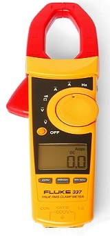


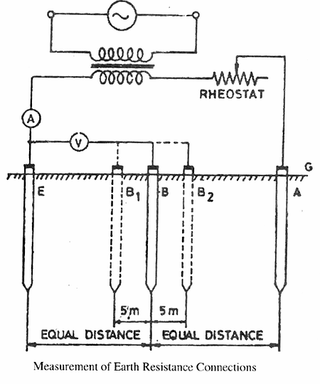


You must be logged in to post a comment.