Circuit Breakers Types

Types of Circuit Breaker and Its Importance

In the electrical and electronics world, there are many cases where mishap takes place. It will lead to severe damage to buildings, offices, houses, schools, industries, etc. Trusting voltage and current are not correct, though safety measures are taken. Once circuit breakers are installed it will control the sudden rise of voltage and current. It will help from any accident. Circuit breakers are like the heart of the electrical system. There are different types of circuit breakers where these are installed according to the rating of the system. In house different kind of circuit breaker is used and for industries, another type of circuit breaker is used. Let us discuss the different types of circuit breakers and their importance in detail.

What is a Circuit Breaker?

An electrical circuit breaker is a switching device that can be operated automatically or manually for protecting and controlling the electrical power system. In the modern power system, the design of the circuit breaker has changed depending upon the huge currents and to prevent from the arc while operating.

Circuit Breaker
Circuit Breaker

The electricity that is coming to the houses or offices or schools or industries or any other places from the power distribution grids forms a large circuit. Those lines which are connected to the power plant forming at one end are called the hot wire and the other lines connecting to the ground forming another end. Whenever the electrical charge flows between these two lines it develops potential between them. For the complete circuit, the connection of loads (appliances) offers resistance to the flow of charge and the whole electrical system inside the house or industries will work smoothly.

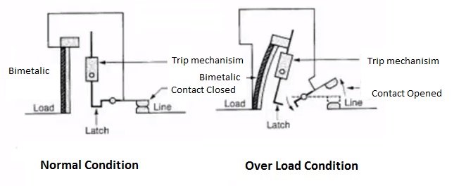
They work smoothly as long as the appliances have sufficiently resistant and do not cause any over current or voltage. The reasons for heating the wires are too much charge flowing through the circuit or short-circuiting or sudden connection of the hot end wire to the ground wire would heat the wires, causing a fire. The circuit breaker will prevent such situations which simply cut off the remaining circuit.

Different Types of Circuit Breakers

The different types of high voltage circuit breakers which include the following

  • Air Circuit Breaker
  • SF6 Circuit Breaker
  • Vacuum Circuit Breaker
  • Oil Circuit Breaker
  • Air Circuit Breaker

Air Circuit Breaker

This circuit breaker will operate in the air; the quenching medium is an Arc at atmospheric pressure. In many of the countries, the air circuit breaker is replaced by an oil circuit breaker. About the oil circuit breaker, we will discuss later in the article. Thus the importance of ACB is still a preferable choice to use an Air circuit breaker up to 15KV. This is because; oil circuit breaker may catch fire when used at 15V

The two types of air circuit breakers are

  • Plain air circuit breaker
  • Airblast Circuit Breaker

Plain Air Circuit Breaker

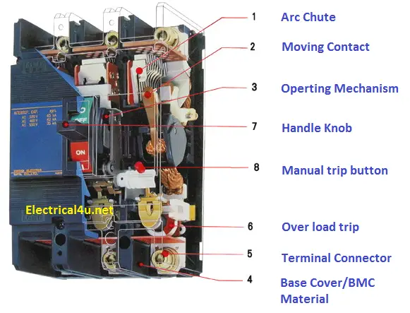
A plain air circuit breaker is also called a Cross-Blast Circuit Breaker. In this, the circuit breaker is fitted with a chamber that surrounds the contacts. This chamber is known as arc chute.

Plain Air Circuit Breaker

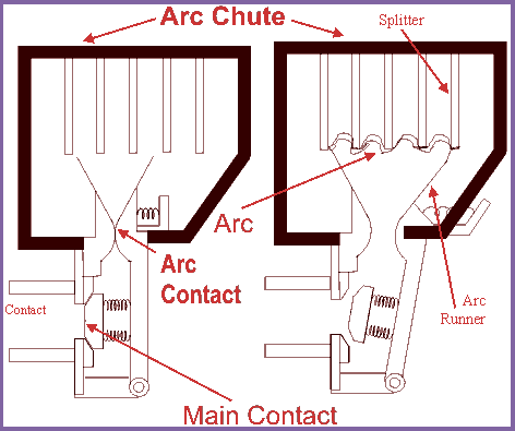
This arc is made to drive in it. In achieving the cooling of the air circuit breaker, an arc chute will help. From the refractory material, an arc chute is made. The internal walls of arc chute are shaped in such a way that arc is not forced into proximity. It will drive into the winding channel projected on an arc chute wall.

The arc chute will have many small compartments and has many divisions which are metallic separated plates. Here each of small compartments behaves as a mini-arc chute and metallic separation plate act like arc splitters. All arc voltages will be higher than the system voltage when the arc will split into a series of arcs. It is only preferable for low voltage applications.

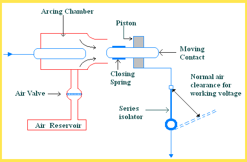
Air Blast Circuit Breaker

Airblast circuit breakers are used for a system voltage of 245 kV, 420 KV and also even more.Airblast circuit breakers are of two types:

  • Axial blast breaker
  • Axial blast with sliding moving contact.

Axial Blast Breaker

In the axial blaster breaker, the moving contact of the axial blast breaker will be in contact. The nozzle orifice is fixed to the contact of a breaker at a normally closed condition. A fault occurs when high pressure is introduced into the chamber. Voltage is sufficient to sustain high-pressure air when flowed through the nozzle orifice.

Axial Blast Circuit breaker
Advantages of Air-Blast Circuit Beaker
  • It is used where frequent operation is required because of lesser arc energy.
  • It is risk-free from fire.
  • Small in size.
  • It requires less maintenance.
  • Arc quenching is much faster
  • The speed of the circuit breaker is much higher.
  • The time duration of the arc is the same for all values of current.
Disadvantages of Air-Blast Circuit Breaker
  • It requires additional maintenance.
  • The air has relatively lower arc extinguishing properties
  • It contains a high capacity air compressor.
  • From the air pipe junction, there may be a chance of air pressure leakage
  • There is the chance of a high rate rise of re-striking current and voltage chopping.

Application and Uses of Air Circuit Breaker

  • It is used for protection of plants, electrical machines, transformers, capacitors, and generators
  • An air circuit breaker is also used in the Electricity sharing system and GND about 15Kv
  • Also used in Low as well as High Currents and voltage applications.

SF6 Circuit Breaker

In the SF6 circuit breaker, the current-carrying contacts operate in sulfur hexafluoride gas is known as an SF6 circuit breaker. It is an excellent insulating property and high electro-negativity. It can be understood that, the high affinity of absorbing free electron. The negative ion is formed when a free electron collides with the SF6 gas molecule; it is absorbed by that gas molecule. The two different ways of attachment of electron with SF6 gas molecules are

SF6 + e = SF6
SF6 + e = SF5- + F

SF6 Circuit Breaker

The negative ions which are formed will be much heavier than a free electron. Therefore, when compared with other common gases overall mobility of the charged particle in the SF6 gas is much less. The mobility of charged particles is majorly responsible for conducting current through a gas. Hence, for heavier and less mobile charged particles in SF6 gas, it acquires very high dielectric strength. This gas good heat transfer property because of low gaseous viscosity. SF6 is 100 times more effective in arc quenching media than an air circuit breaker. It is used for both medium and high voltage electrical power system from 33KV to 800KV.

Types of SF6 Circuit Breaker

  • Single interrupter SF6 circuit breaker applied up to 220
  • Two interrupters SF6 circuit breaker applied up to 400
  • Four interrupters SF6 circuit breaker applied up to 715V

Vacuum Circuit Breaker

A Vacuum circuit breaker is a circuit in which a vacuum is used to extinct the arc. It has dielectric recovery character, excellent interruption, and can interrupt the high-frequency current which results from arc instability, superimposed on the line frequency current.

Vacuum Circuit Breaker

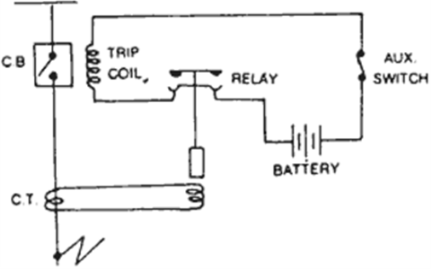
The principle of operation of VCB will have two contacts called electrodes will remain closed under normal operating conditions. Suppose when a fault occurs in any part of the system, then the trip coil of the circuit breaker gets energized and finally, the contact gets separated.

The moment contacts of the breaker are opened in a vacuum, i.e. 10-7 to 10-5 Torr an arc is produced between the contacts by the ionization of metal vapors of contacts. Here the arc quickly gets extinguished, this happens because the electrons, metallic vapors, and ions produced during the arc, condense quickly on the surface of the CB contacts, resulting in quick recovery of dielectric strength.

Advantages

  • VCBs are reliable, compact and long life
  • They can interrupt any fault current.
  • There will be no fire hazards.
  • No noise is produced
  • It has a higher dielectric strength.
  • It requires less power for control operation.

Oil Circuit Breaker

In this type of circuit, breaker oil is used, but mineral oil is preferable. It acts better insulating property than air. The moving contact and fixed contact are immersed inside the insulating oil. When the separation of current takes place, then carrier contacts in the oil, the arc in the circuit breaker is initialized at the moment of separation of contacts, and because of this arc in the oil is vaporized and decomposed in hydrogen gas and finally creates a hydrogen bubble around the arc.

This highly compressed gas bubble around and arc prevents re-striking of the arc after the current reaches zero crossings of the cycle. The OCB is the oldest type of circuit breakers.

Different types of Oil Circuit Breaker

  • Bulk oil circuit breaker
  • Minimum oil circuit breaker

Bulk Oil Circuit Breaker (BOCB)

In the BOCB, oil is used to arc the quenching media and also for insulating media in between earth parts of circuit breaker and current-carrying contacts. The same transformer insulating oil is used.

The working principle of the BOCB says when the current-carrying contacts in the oil are separated, then an arc is generated between the separated contacts. The arc which is established will produce rapidly growing gas bubble around the arc. The moving contacts will move away from the fixed contact of arc and this result the resistance of the arc gets increased. Here the increased resistance will cause lowering the temperature. Hence the reduced formations of gasses surround the arc.

BOB Circuit Breaker

When the current passes through zero-crossing the arc quenching in the BOCB takes place. In the totally airtight vessel, the gas bubble is enclosed inside the oil. The oil will surround with high pressure on the bubble, this results in highly compressed gas around the arc. When the pressure is increased the deionization of the gas also increases, which results in arc quenching. The hydrogen gas will help in cooling the arc quenching in the oil circuit breaker.

Advantages
  • Good cooling property because of decomposition
  • Oil has high dielectric strength
  • It acts as an insulator between earth and live parts.
  • The oil used here will absorb arc energy while decomposing
Disadvantages
  • It will not permit high speed of interruption
  • It takes a long arcing time.

Minimum Oil Circuit Breaker

It is a circuit breaker that utilizes oil as the interrupting media. The minimum oil circuit breaker will place the interrupting unit in an insulating chamber at the live potential. But insulating material is available in the interrupting chamber. It requires less amount of oil so it is called a minimum oil circuit breaker.

Minimum Oil Circuit Breaker
Advantages
  • It requires less maintenance.
  • It is suitable for both automatic operation and manual.
  • It requires a smaller space
  • The cost of breaking capacity in MVA is also less.
Disadvantages
  • Oil deteriorates because of carbonization.
  • There is a possibility of explosion and fire
  • As it has a smaller quantity of oil, so carbonization increases.
  • It is very difficult to remove gases from the space between the contacts.

Rating: 5 out of 5.

MCCB Applications

MCCB (Moulded Case Circuit Breaker) Working, Types, Rating

MCCB (Moulded Case Circuit Breaker) Working, Types, Rating

What is MCCB – Moulded case circuit breaker:

Moulded case circuit breaker is a full form of MCCB in electrical. MCCB is an automatic electrical device used to protect the electrical equipment from overload, short circuit, instantaneous over current and earth fault. It is an advanced version of MCB (Miniature circuit breaker). It is available from 32 Amps to 1600 Amps with the voltage range of 230V to 1.1kV.https://c414c0e4124ff6963e9764cf20faba5f.safeframe.googlesyndication.com/safeframe/1-0-37/html/container.html

The main advantage of MCCB (Moulded case circuit breaker) is that we can tailor it as per our requirement by installing with new future such as remote closing, UV trip etc. It is the best replacement for an air circuit breaker in terms of cost as well as better function. Also, you can adjust the current setting as well as the time setting in the moulded case circuit breaker.

Single Line Diagram:

Moulded case circuit breaker is indicated by a small curve followed by the two lines

Single Line Diagram
Single Line Diagram
The input and output of the moulded case circuit will be bottom and top side.

Construction:

MCCB Consists of 9 different parts such

1.Arc chute

2.Moving Contact

3.Operating mechanism

4.Base cover

5.Terminal Connector

6.Overload trip or Bimetallic contact

7.Handle knob

8.Manual trip button

9.CT – Current Transformer assembly

Let’s see the detailed explanation of the construction of MCCB. Before refer the picture.

MCCB Construction

Arc chute:

It is a stack of mutually insulated parallel metal plates that used to divide the arc being developed in the moulded case circuit breaker. Arc chute material is made up of steel and glass fiber material.

Moving contact:

An electrolyzed brass material is used as a moving contact. The MOC (Material of Construction) of the moving contact should be high arc resistance, corrosion resistance, low resistivity etc. The MOC decides the life span of the MCCB.

Operating mechanism:

It deals with the contact opening and closing process. The speed of the operating mechanism does not depend on how fast the handle is moved. It is called a quick make and quick break.

It will be associated with the relay operating mechanism.

Also, breakers are designed with the test mechanism which allows the breaker to trip manually.

Base Cover:

A closed assembly of glass-fiber reinforced thermoset polymer material primarily used as a base cover of the Moulded case circuit breaker. It gives better mechanical strength. All the parts of the MCCB will be mount inside of these covers.

Terminal connector

The terminal connector is a bolt assembly, made up of steel material. It is used to connect the external circuit with the MCCB. Generally, Allen’s head (hexagonal) with 8.8 Ton torque range bolts is used as a terminal connector. It ensures there is no loose contact between the terminal.

If the rating of the MCCB is more than 400Amps means, the terminal connector will be equipped with an assembly called spreader links.

They are used to connect MCCB with the higher rating cables since the cable size will be bigger for the higher current ratings.

Bimetallic Contact:

A temperature-sensitive component, the composition of steel and copper material is used as bimetallic contact. Bimetallic contact is assembled in series with the line current.

Hence, the full line current of the breaker always will be passed through the bimetallic contact.

It is used to trip the breaker under an overload condition.

Handle Knob:

It is used to close or open the contact manually. Also, you cannot force to stop the breaker tripping by holding knob at the top side. It is called a free trip.

Handle knob indicates the breaker status, whether it is in ON position or OFF position.

If the handle is in the upward direction, it is called ON position, if it is in the downward position, the same called off position. If it is tripped, then the handle would be in the center position.

Manual trip button:

A red color button that is associated with the operating mechanism is called a manual trip button. It is mainly used to trip the breaker manually for testing purposes.

Current Transformer & Trip unit assembly:

MCCB CT Arrangement
MCCB CT Arrangement

A set of current transformer is mount inside of the breaker as shown in the above-mentioned figure,

The output of the CT will be connected to the relay tripping unit. It is the brain of the MCCB.

The tripping unit contains an electromagnetic coil associated with the tripping plunger. The electromagnetic coil is used to trip the breaker with a predefined time delay during a short circuit, earth fault, and instantaneous fault condition.

Working Principle:

The MCCB working principle is simple. Let us take three different fault conditions such as Overload, short circuit, and earth fault.

Overload trip

A flow of current that exceeds the rated current with predefined time limit such a fault is called overload. Actually, it is not a fault, it is a condition.

The bimetallic contact involves in overload operation of the breaker; under the normal condition, it allows the current flow. If the current flow exceeds the predefined value, then it will get bend and finally, it will engage the tripping mechanism. The trip mechanism opens the breaker. Refer to the picture below mentioned

Bimetallic Contact Operation

Also, bimetallic contact will not allow the breaker to reset instantly. Since it takes some time to reach its original state.

Over Load, the setting will be 80% to 100% of the full load current and the dame depending upon your load demand. But the time delay will be 10 to 15secs.

Short circuit / instantaneous/earth fault trip:

An electromagnetic coil involves short circuit/instantaneous/earth fault protection of the breaker. Under normal conditions, the CT generates less current hence the electromagnetic field is generated by the coil is not enough to pull the plunger. Therefore, the breaker does not trip.

During short circuit or instantaneous fault conditions, the CT generates high current and the coil creates a strong magnetic field. Hence the coil pulls the plunger and it will trip the circuit instantly.

The typical setting of a short circuit will be 2.5Times of the overload setting and the time delay will be 0.2 to 0.5 secs.

The typical setting of an instantaneous fault will be 4 Times of the overload setting and the time delay will be zero.

Earth Fault leakage trip:

Earth leakage protection is quite different from other protection. It a tailor-made one. It requires additional CT which has to be installed in the moulded case circuit breaker.

The output of the current transformer will be connected in star. Under normal conditions, the current flow through the star’s neural point will be zero. if the leakage found in the line means, the same will be sensed at the star terminal. if the leakage flow is higher than the allowable limit means, the MCCB trip the circuit.

Types of MCCB

According to the tripping types, the MCCB is divided into six categories.

TypeB: They are operating at the fault current reaches 3 to 5 times the full load current. It is used for domestic applications such as resistive load, lighting loads, etc. The available operating time of this beaker is 0.04 to 15 seconds

TypeC: Type C breaker specially used for inductive loads, such as transformers, welding machines, electromagnets etc. it has an operating range of 5 to 8 times the full load current with the time delay of 0.04 to 5seconds.

TypeD: Suitable for heavy starting current applications such as motors, pumps, lifts, etc. It has an operating range of 10 to 15 times with the time duration of 0.04 to 3 seconds

TypeK: Operates when the current goes to 8 to 10 times its full load current. Operating time for type K MCCB is 0.04 to 5 Seconds. They are the best suitable feeder protection.

TypeZ: Type Z MCCBs are very sensitive and they can able to allow 1.5 to 3 times the full load current. Type Z is suitable for electronics load, whereas high-speed tripping required.

Shunt Coil in MCCB

Shunt Coil 220vac

MCCB rating

The manufacture provides some technical data that is used to understand the characteristics of the MCCB. Let us see.

Inm – rated Frame current => the maximum allowable current through the MCCB whereas MCCB operates under the stable region.

In => Rated current => Functional tripping range of the breaker.

Ui => Rated Insulation Voltage => the maximum allowable voltage ranges of the breaker.

Ue => Rated Voltage => Functional voltage of the breaker

Uimp => Rated Impulse Withstand voltage => Surge Voltage of the MCCB, the standard size for impulse testing is 1.2/50µs

Ics => Short circuit Breaking Capacity => The maximum amount of short circuit current where the breaker can break the circuit without physical damage.

Ics => Unlimited short circuit breaking capacity => The maximum breaking capacity of the MCCB whereas the MCCB can break the circuit with the physical damage. Beyond that limit, it will not operate

Advantage

  • Occupy less space in the electrical panel
  • Cheaper than ACBs
  • Adjustable current settings
  • Maintenance-free
  • Fault clearing times are faster than the fuse units.
  • No need to keep the spares, hence the inventory will be reduced.
  • Suitable for industrial and commercial applications

Disadvantages

  • LISG fault needs to tailor it.
  • Needs additional add-on for getting feedback from the MCCB.
  • Not suitable domestic application.
  • Life span is less as compared with ACBs
  • Not suitable for high voltage applications.

Applications:

  • I have used it for many induction motor’s starters such as star-delta, DOL starter, Soft starter etc,
  • Panel incomer applications,
  • Distribution feeder

Frequently Asked Questions

  1. Can we use it for the DC application?

Yes, we can use it, but it will not trip on short circuit fault.

2. Best suitable type MCCB for the star-delta starter?

Type D, since the operating range is high, they can tolerate the high starting current of the induction motor.

3. How to choose the MCCB?

While purchasing MCCB, you have to take care of rated full load current, types of mccb, Ics.

4. Who is the best manufacture of MCCB?

Siemens is the best one. I have used in my many applications, they are user friendly.

5. How to reset the MCCB:

While tripping the MCCB, the handle knob will be in the middle position, in order to reset the breaker, pull the knob at the downside. It will get reset.

Rating: 5 out of 5.

Vacuum Circuit Breaker (VCB)

A vacuum circuit breaker is such kind of circuit where the arc queching takes place in vacuum. The technology is suitable for mainly medium oltage application. For higher voltage vacuum technology has been developed but not commercially viable. The operation of opening and closing of current carrying contacts and associated tarc interruption ake place in a vacuum chamber in the breaker which is called vacuum interrupter.

Vacuum Interrupter cut way view

The vacuum interrupter consists of a steel arc chamber in the centre symmetrically arranged ceramic insulators. The vacuum pressure inside a vacuum interrupter is normally maintained at 10– 6 bar.

The material used for current carrying contacts plays an important role in the performance of the vacuum circuit breaker. Cu/Cr is the ideal material to make VCB contacts. Vacuum interrupter technology was first introduced in the year 1960. But still, it is a developing technology.

As time goes on, the size of the vacuum interrupter is being reduced from its early 1960’s size due to different technical developments in this field of engineering. The contact geometry is also improving with time, from butt contact of early days it gradually changes to spiral shape, cup shape and axial magnetic filed contact. The vacuum circuit breaker is today recognized as most reliable current interruption technology for medium voltage switchgear. It requires minimum maintenance compared to other circuit brealer technologies.

Advantages of Vacuum Circuit Breaker or VCB

Service life of vacuum circuit breaker is much longer than other types of circuit breakers. There is no chance of fire hazard like oil circuit brealer. It is much environment friendly than SF6 circuit breaker. Beside that contraction of VCB is user-friendly. Replacement of vacuum interrupter (VI) is much convenient.

Operation of Vacuum Circuit Breaker

The main aim of any circuit brealer is to quench arc during current zero crossing, by establishing high dielectric strength in between the contacts so that reestablishment of arc after current zero becomes impossible.

The dielectric strength of vacuum is eight times greater than that of air and four times greater than that of SF6 gas. This high dielectric strength makes it possible to quench a vacuum SF6 within very small contact gap. For short contact gap, low contact mass and no compression of the medium the drive energy required in vacuum circuit breaker is minimum.

When two face to face contact areas are just being separated to each other, they do not be separated instantly, the contact area on the contact face is being reduced and ultimately comes to a point and then they are finally de-touched. Although this happens in a fraction of microsecond, it is a fact.

At this instant of de-touching of contacts in a vacuum, the current through the contacts concentrated on that last contact point on the contact surface and makes a hot spot.

As it is a vacuum, the metal on the contact surface is easily vaporized due to that hotspot and create a conducting media for arc path. Then the arc will be initiated and continued until the next current zero.
vacuum interrupter

Cross section of Vacuum interrupter


At current zero this vacuum arc is extinguished and the conducting metal vapor is re-condensed on the contact surface. At this point, the contacts are already separated hence there is no question of re-vaporization of the contact surface, for the next cycle of current. That means, the arc cannot be reestablished again. In this way vacuum circuit breaker prevents the reestablishment of arc by producing high dielectric strength in the contact gap after current zero.

There are two types of arc shapes. For interrupting current up to 10 kA, the arc remains diffused and the form of vapor discharge and cover the entire contact surface. Above 10 kA the diffused arc is constricted considerably by its own magnetic field and it contracts.

The phenomenon gives rise overheating of contact at its center. In order to prevent this, the design of the contacts should be such that the arc does not remain stationary but keeps traveling by its own magnetic field. Specially designed contact shape of vacuum circuit breaker makes the constricted stationary arc travel along the surface of the contacts, thereby causing minimum and uniform contact erosion.

Rating: 5 out of 5.

Air Circuit Breaker(ACB)

ACBs) are used as circuit protection for a wide range of low voltage (up to 600V AC) applications, typically generators, MCCB distribution boards, UPS, small power stations, etc with sizes ranging from 400A to 6300A or larger. Protection is provided in either 3 or 4 pole configurations. Additional protective devices can be fitted such as undervoltage releases and shunt trip coils together with auxiliary contacts for remote signalling. 

Maintenance :-ACBs are the cause of almost 20% of power distribution system failures, mainly due to lack of maintenance, dust, hardened grease, corrosion and/or frozen parts that prevent the proper operation of the trip linkage. It wasn’t long ago that ageing electrical equipment was replaced but in today’s business environment, maintenance is the preferred choice to ensure reliable operation and extend the life expectancy.

Removing the withdrawable ACB front Cover

As with all electro-mechanical devices, major electrical equipment manufacturers recommend maintenance of air circuit breakers to ensure proper operation and to maintain equipment warranties. With regular service air circuit breakers can remain in service almost indefinitely as long as spare parts are readily available.

1.Visual inspection for any broken parts and replace as needed. Clean and lubricate all mechanical linkages.

2.Inspect all breakers, remove all covers and arc extinguishing shields, inspect for damage, wear and deterioration, clean and lubricate as required. Check, clean and dress (if required) the main contacts, clean all covers and arc shields.

3.Check security of all control wiring and associated fitted components, prove mechanical operations and reinstate covers and arc extinguishing shields.

4.Carry out insulation test, phase to phase and phase to earth.

5.Prove mechanical and electrical operation of the breaker by racking breaker to test position and carrying out injection test on electronic trip devices to prove operating characteristics against set points.

6.Rack breaker to connect position and return breaker to service condition.

ACB relay Details:-

Rating: 5 out of 5.

Design a site like this with WordPress.com
Get started