Series Wound DC Motor or DC Series Motor

A series wound DC motor like in the case of shunt wound DC motor or compound wound DC motor falls under the category of self-excited DC motors, and it gets its name from the fact that the field winding in this case is connected internally in series to the armature winding. Thus the field winding are exposed to the entire armature current unlike in the case of a shunt motor.

Construction of Series DC Motor

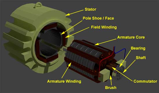
Construction wise a this motor is similar to any other types of DC motors in almost all aspects. It consists of all the fundamental components like the stator housing the field winding or the rotor carrying the armature conductors, and the other vital parts like the commutator or the brush segments all attached in the proper sequence as in the case of a generic DC motor.

Yet if we are to take a close look into the wiring of the field and armature coils of this DC motor, its clearly distinguishable from the other members of this type.
To understand that let us revert back into the above mentioned basic fact, that the this motor has field coil connected in series to the armature winding. For this reason relatively higher current flows through the field coils, and its designed accordingly as mentioned below.

  • The field coils of DC series motor are wound with relatively fewer turns as the current through the field is its armature current and hence for required mmf less numbers of turns are required.
  • The wire is heavier, as the diameter is considerable increased to provide minimum electrical resistance to the flow of full armature current.
  • In spite of the above mentioned differences, about having fewer coil turns the running of this DC motor remains unaffected, as the current through the field is reasonably high to produce a field strong enough for generating the required amount of torque. To understand that better lets look into the voltage and current equation of DC series motor.

Voltage and Current Equation of Series DC Motor

series dc motor

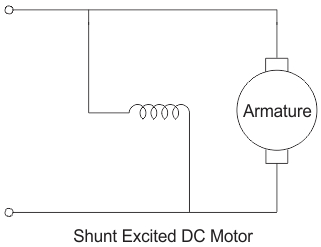
The electrical layout of a typical series wound DC motor is shown in the diagram below.

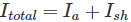
Let the supply voltage and current given to the electrical port of the motor be given by E and Itotal respectively.
Since the entire supply current flows through both the armature and field conductor.

Where, Ise is the series current in the field coil and Ia is the armature current.
Now form the basic voltage equation of the DC motor.

Where, Eb is the back emf.
Rse is the series coil resistance and Ra is the armature resistance.
Since Ise = Ia, we can write,

This is the basic voltage equation of a series wound DC motor.
Another interesting fact about the DC series motor worth noting is that, the field flux like in the case of any other DC motor is proportional to field current.

But since here

i.e. the field flux is proportional to the entire armature current or the total supply current. And for this reason, the flux produced in this motor is strong enough to produce sufficient torque, even with the bare minimum number of turns it has in the field coil.

Speed and Torque of Series DC Motor

A series wound motors has linear relationship existing between the field current and the amount of torque produced. i.e. torque is directly proportional to current over the entire range of the graph. As in this case relatively higher current flows through the heavy series field winding with thicker diameter, the electromagnetic torque produced here is much higher than normal. This high electromagnetic torque produces motor speed, strong enough to lift heavy load overcoming its initial inertial of rest. And for this particular reason the motor becomes extremely essential as starter motors for most industrial applications dealing in heavy mechanical load like huge cranes or large metal chunks etc. Series motors are generally operated for a very small duration, about only a few seconds, just for the purpose of starting. Because if its run for too long, the high series current might burn out the series field coils thus leaving the motor useless.

Speed Regulation of Series Wound DC Motor

series motor characteristic

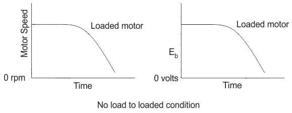
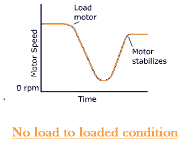
Unlike in the case of a DC shunt motor, the DC series motor has very poor speed regulation. i.e. the series motor is unable to maintain its speed on addition of external load to the shaft. Let us see why?
When mechanical load is added to the shaft at any instance, the speed automatically reduces whatever be the type of motor. But the term speed regulation refers to the ability of the motor to bring back the reduced speed to its original previous value within reasonable amount of time. But this motor is highly incapable of doing that as with reduction in speed N on addition of load, the back emf given by,


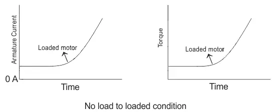
This decrease in back Emf Eb, increases the net voltage E – Eb, and consequently the series field current increases,

The value of series current through the field coil becomes so high that it tends to saturate of the magnetic core of the field. As a result the magnetic flux linking the coils increases at a much slower rate compared to the increase in current beyond the saturation region as shown in the figure below.
The weak magnetic field produced as a consequence is unable to provide for the necessary amount of force to bring back the speed at its previous value before application of load.
So keeping all the above mentioned facts in mind, a series wound DC motor is most applicable as a starting motor for industrial applications.

Rating: 5 out of 5.

Three Phase Induction Motor Definition & Working Principle

An electrical motor is an electromechanical device which converts electrical energy into mechanical energy. In the case of three phase AC (Alternating Current) operation, the most widely used motor is a 3 phase induction motor, as this type of motor does not require an additional starting device. These types of motors are known as self-starting induction motors.

To get a good understanding of the working principle of a three phase induction motor, it’s essential to understand the construction of a 3 phase induction motor. A 3 phase induction motor consists of two major parts:

  • A stator
  • A rotor

Stator of 3 Phase Induction Motor

The stator of three phase induction motor is made up of numbers of slots to construct a 3 phase winding circuit which we connect with 3 phase AC source. We arrange the three-phase winding in such a manner in the slots that they produce one rotating magnetic field when we switch on the three-phase AC supply source.

Rotor of 3 Phase Induction Motor

The rotor of three phase induction motor consists of a cylindrical laminated core with parallel slots that can carry conductors. The conductors are heavy copper or aluminum bars fitted in each slot and short-circuited by the end rings. The slots are not exactly made parallel to the axis of the shaft but are slotted a little skewed because this arrangement reduces magnetic humming noise and can avoid stalling of the motor.

Working of Three Phase Induction Motor

Production of Rotating Magnetic Field

The stator of the motor consists of overlapping winding offset by an electrical angle of 120o. When we connect the primary winding, or the stator to a 3 phase AC source, it establishes rotating magnetic field which rotates at the synchronous speed.

Secrets Behind the Rotation:
According to Faraday’s law an emf induced in any circuit is due to the rate of change of magnetic flux linkage through the circuit. As the rotor winding in an induction motor are either closed through an external resistance or directly shorted by end ring, and cut the stator rotating magnetic field, an emf is induced in the rotor copper bar and due to this emf a current flows through the rotor conductor.

Here the relative speed between the rotating flux and static rotor conductor is the cause of current generation; hence as per Lenz’s law, the rotor will rotate in the same direction to reduce the cause, i.e., the relative velocity.

Thus from the working principle of three phase induction motor, it may be observed that the rotor speed should not reach the synchronous speed produced by the stator. If the speeds become equal, there would be no such relative speed, so no emf induced in the rotor, and no current would be flowing, and therefore no torque would be generated. Consequently, the rotor cannot reach the synchronous speed. The difference between the stator (synchronous speed) and rotor speeds is called the slip. The rotation of the magnetic field in an induction motor has the advantage that no electrical connections need to be made to the rotor.

Thus the three phase induction motor is:

  • Self-starting.
  • Less armature reaction and brush sparking because of the absence of commutators and brushes that may cause sparks.
  • Robust in construction.
  • Economical.
  • Easier to maintain.

Rating: 5 out of 5.

Testing of Induction Motor

Demand of energy is growing day by day and along with it cost of energy rising abruptly, so now it is necessary that the health of large motors which consumes maximum power should be taken care off. Tests are required to check the condition of the induction motor and to get the basic idea of malfunctioning of the motor. Now a day lots of techniques and tests are available which gives the complete health card of the induction motors. By monitoring some parameters like voltage, current, temperature, and vibration problem could be diagnosed and by correcting these faults the overall efficiency of the machine can be improved. This will reduce the energy consumption and operational costs.

Basic Parameters to be Checked

Current
As line current in all the phases are not equal so the arithmetic mean of the phase currents should be used for evaluating machine performance.

Voltage
voltage is measured at the motor terminals and at the time of test, it should be approximately balanced. Machine performance can be calculated by using average of the phase voltages.

Power
power input to three phase motor can be calculated by a single watt meters as they are connected in two watt meter method.

Resistance
It is necessary to check the ground resistance between the motor body and terminals of the machine.

Tests for Induction Motor

Number of test is done on induction motor to check its different parameters. All the tests are divided into two parts:

Preliminary Tests

These tests are performed to check the electrical or mechanical defects of the induction motor.

1.Firstly check the components of motor like

1a.Broken rotor bars

1b.High resistance joints

1c.Cracked end rings

2.No-load running current test

3.High potential test

4.Air-gap measurement

5.Balancing of current

6.Temperature rise in bearing

7.Voltages in shaft

8.Direction of rotation

9.Level of noise

10.Strength of vibration

11.Air gap eccentricity

Performance Tests

The purpose of these tests is to estimate the performance characteristics of the induction motor. Along with preliminary tests, these tests are also done on motor.

1.No load test

2.Locked rotor test

3.Breakdown torque load performance test

4.Temperature test

5.Stray load loss test

6.Determination of efficiency test

Rating: 5 out of 5.

Induction Motor: Working Principle, Types, & Definition

What is an Induction Motor?

An induction motor (also known as an asynchronous motor) is a commonly used AC electric motor. In an induction motor, the electric current in the rotor needed to produce torque is obtained via electromagnetic induction from the rotating magnetic field of the stator winding. The rotor of an induction motor can be a squirrel cage rotor or wound type rotor.

Induction motors are referred to as ‘asynchronous motors’ because they operate at a speed less than their synchronous speed. So first thing to understand – what is synchronous speed?

A Typical Induction Motor

Synchronous Speed

Synchronous speed is the speed of rotation of the magnetic field in a rotary machine, and it depends upon the frequency and number poles of the machine. The induction motor always runs at speed less than its synchronous speed. The rotating magnetic field produced in the stator will create flux in the rotor, hence causing the rotor to rotate. Due to the lag between the flux current in the rotor and the flux current in the stator, the rotor will never reach its rotating magnetic field speed (i.e. the synchronous speed).

There are basically two types of induction motor. The types of induction motor depend upon the input supply. There are single phase induction motors and three phase induction motors. Single phase induction motors arenot a self-starting motor, and three phase induction motor are a self-starting motor.

Working Principle of Induction Motor

We need to give double excitation to make a DC motor to rotate. In the DC motor, we give one supply to the stator and another to the rotor through brush arrangement. But in induction motor, we give only one supply, so it is interesting to know how an induction motor works. It is simple, from the name itself we can understand that here, the induction process is involved. When we give the supply to the stator winding, a magnetic flux gets produced in the stator due to the flow of current in the coil. The rotor winding is so arranged that each coil becomes short-circuited.

The flux from the stator cuts the short-circuited coil in the rotor. As the rotor coils are short-circuited, according to Faraday’s law of electromagnetic induction, the current will start flowing through the coil of the rotor. When the current through the rotor coils flows, another flux gets generated in the rotor. Now there are two fluxes, one is stator flux, and another is rotor flux. The rotor flux will be lagging in respect of the stator flux. Because of that, the rotor will feel a torque which will make the rotor to rotate in the direction of the rotating magnetic field. This is the working principle of both single and three phase induction motors.

Types of Induction Motors

The types of induction motors can be classified depending on whether they are a single phase or three phase induction motor.

Single Phase Induction Motor

The types of single phase induction motors include:

  1. Split Phase Induction Motor
  2. Capacitor Start Induction Motor
  3. Capacitor Start and Capacitor Run Induction Motor
  4. Shaded Pole Induction Motor

Three Phase Induction Motor

The types of three phase induction motors include:

  1. Squirrel Cage Induction Motor
  2. Slip Ring Induction Motor

We have already mentioned above that the single-phase induction motor is not a self-starting motor, and that the three-phase induction motor is self-starting. So what is a self-starting motor?

When the motor starts running automatically without any external force applied to the machine, then the motor is referred to as ‘self-starting’. For example, we see that when we put on the switch the fan starts to rotate automatically, so it is a self-starting machine. Point to be noted that fan used in home appliances is a single phase induction motor which is inherently not self-starting. How? Does a question arise as to how it works? We will discuss it now.

Why is Three Phase Induction Motor Self Starting?

In a three phase system, there are three single phase lines with a 120° phase difference. So the rotating magnetic field has the same phase difference which will make the rotor to move. If we consider three phases a, b, and c when phase a gets magnetized, the rotor will move towards the phase a winding a, in the next moment phase b will get magnetized and it will attract the rotor and then phase c. So the rotor will continue to rotate.

Rating: 5 out of 5.

Synchronous Motors: Applications, Starting Methods & Working Principle

Electrical motors are an electro-mechanical device that converts electrical energy to mechanical energy. Based on the type of input we have classified it into single phase and 3 phase motors.

The most common type of 3 phase motors are synchronous motors and induction motors. When three-phase electric conductors are placed in certain geometrical positions (i.e. in a certain angle from one another) – an electrical field is generated. The rotating magnetic field rotates at a certain speed known as the synchronous speed.

If an electromagnet is present in this rotating magnetic field, the electromagnet is magnetically locked with this rotating magnetic field and rotates with the same speed of rotating field.

This is where the term synchronous motor comes from, as the speed of the rotor of the motor is the same as the rotating magnetic field.

It is a fixed speed motor because it has only one speed, which is synchronous speed. This speed is synchronised with the supply frequency. The synchronous speed is given by:

Where:

  • N= The Synchronous Speed (in RPM – i.e. Rotations Per Minute)
  • f = The Supply Frequency (in Hz)
  • p = The number of Poles

Construction of Synchronous Motor

Usually, its construction is almost similar to that of a 3 phase induction motor, except the fact that here we supply DC to the rotor, the reason of which we shall explain later. Now, let us first go through the basic construction of this type of motor. From the above picture, it is clear that how do we design this type of machine. We apply three phase supply to the stator and DC supply to the rotor.

Main Features of Synchronous Motors

  • Synchronous motors are inherently not self starting. They require some external means to bring their speed close to synchronous speed to before they are synchronized.
  • The speed of operation of is in synchronism with the supply frequency and hence for constant supply frequency they behave as constant speed motor irrespective of load condition
  • This motor has the unique characteristics of operating under any electrical power factor. This makes it being used in electrical power factor improvement.

Principle of Operation Synchronous Motor

Synchronous motors are a doubly excited machine, i.e., two electrical inputs are provided to it. Its stator winding which consists of a We provide three-phase supply to three-phase stator winding, and DC to the rotor winding.

The 3 phase stator winding carrying 3 phase currents produces 3 phase rotating magnetic flux. The rotor carrying DC supply also produces a constant flux. Considering the 50 Hz power frequency, from the above relation we can see that the 3 phase rotating flux rotates about 3000 revolutions in 1 min or 50 revolutions in 1 sec.

At a particular instant rotor and stator poles might be of the same polarity (N-N or S-S) causing a repulsive force on the rotor and the very next instant it will be N-S causing attractive force. But due to the inertia of the rotor, it is unable to rotate in any direction due to that attractive or repulsive forces, and the rotor remains in standstill condition. Hence a synchronous motor is not self-starting.

Here we use some mechanical means which initially rotates the rotor in the same direction as the magnetic field to speed very close to synchronous speed. On achieving synchronous speed, magnetic locking occurs, and the synchronous motor continues to rotate even after removal of external mechanical means.

But due to the inertia of the rotor, it is unable to rotate in any direction due to that attractive or repulsive forces, and the rotor remains in standstill condition. Hence a synchronous motor is not self-starting.

Here we use some mechanical means which initially rotates the rotor in the same direction as the magnetic field to speed very close to synchronous speed. On achieving synchronous speed, magnetic locking occurs, and the synchronous motor continues to rotate even after removal of external mechanical means.

Methods of Starting of Synchronous Motor

  • Motor starting with an external prime Mover: Synchronous motors are mechanically coupled with another motor. It could be either 3 phase induction motor or DC shunt motor. Here, we do not apply DC excitation initially. It rotates at speed very close to its synchronous speed, and then we give the DC excitation. After some time when magnetic locking takes place supply to the external motor is cut off.
  • Damper winding In this case, the synchronous motor is of salient pole type, additional winding is placed in rotor pole face. Initially, when the rotor is not rotating, the relative speed between damper winding and rotating air gap flux is large and an emf is induced in it which produces the required starting torque. As speed approaches synchronous speed, emf and torque are reduced and finally when magnetic locking takes place; torque also reduces to zero. Hence in this case synchronous motor first runs as three phase induction motor using additional winding and finally it is synchronized with the frequency.

Application of Synchronous Motors

  • Synchronous motor having no load connected to its shaft is used for power factor improvement. Owing to its characteristics to behave at any electrical power factor, it is used in power system in situations where static capacitors are expensive.
  • Synchronous motor finds application where operating speed is less (around 500 rpm) and high power is required. For power requirement from 35 kW to 2500 KW, the size, weight and cost of the corresponding three phase induction motor is very high. Hence these motors are preferably used. Ex- Reciprocating pump, compressor, rolling mills etc.

Rating: 5 out of 5.

Compound Wound DC Motor or DC Compound Motor

A compound wound DC motor (also known as a DC compound motor) is a type of self-excited motor, and is made up of both series the field coils S1 S2 and shunt field coils F1 F2 connected to the armature winding as shown in the figure below.

DC compound motor

Both the field coils provide for the required amount of magnetic flux, that links with the armature coil and brings about the torque necessary to facilitate rotation at the desired speed. As we can understand, a compound wound DC motor is basically formed by the amalgamation of a shunt wound DC motor and series wound DC motor to achieve the better off properties of both these types. Like a shunt wound DC motor is bestowed with an extremely efficient speed regulation characteristic, whereas the DC series motor has high starting torque.

So the compound wound DC motor reaches a compromise in terms of both these features and has a good combination of proper speed regulation and high starting torque.

Though its starting torque is not as high as in case of DC motor, nor is its speed regulation as good as a shunt DC motor. Overall characteristics of DC shunt motor falls somewhere in between these 2 extreme limits.

Types of Compound Wound DC Motor

The compound wound DC motor can further be subdivided into 2 major types on the basis of its field winding connection with respect to the armature winding, and they are:

Long Shunt Compound Wound DC Motor

dc compound motor

In case of long shunt compound wound DC motor, the shunt field winding is connected in parallel across the series combination of both the armature and series field coil, as shown in the diagram below.

Voltage and Current Equation of Long Shunt Compound Wound DC Motor

Let E and Itotal be the total supply voltage and current supplied to the input terminals of the motor. And Ia, Ise , Ish be the values of current flowing through armature resistance Ra, series winding resistance Rse and shunt winding resistance Rsh respectively.
Now we know in shunt motor,
And in series motor

Therefore, the current equation of a compound wound DC motor is given by

And its voltage equation is,

Short Shunt Compound Wound DC Motor

dc compound motor

In case of short shunt compound wound DC motor, the shunt field winding is connected in parallel across the armature winding only. And series field coil is exposed to the entire supply current, before being split up into armature and shunt field current as shown in the diagram below.

Voltage and Current Equation of Short Shunt Compound Wound DC Motor

Here also let, E and Itotal be the total supply voltage and current supplied to the input terminals of the motor. And Ia, Ise, Ish be the values of current flowing through armature resistance Ra, series winding resistance Rse and shunt winding resistance Rsh respectively.
But from the diagram above we can see,

Since the entire supply current flows through the series field winding.
And like in the case of a DC shunt motor,

Equation (2) and (3) gives the current equation of a short shunt compound wound DC motor.
Now for equating the voltage equation, we apply Kirchoff’s law to the circuit and get,

But since
Thus the final voltage equation can be written as,

Apart from the above mentioned classification, a compound wound DC motor can further be sub divided into 2 types depending upon excitation or the nature of compounding. i.e.

Cumulative Compounding of DC Motor

A compound wound DC motor is said to be cumulatively compounded when the shunt field flux produced by the shunt winding assists or enhances the effect of main field flux, produced by the series winding.

Differential Compounding of DC Motor

dc motor characteristics

Similarly a compound wound DC motor is said to be deferentially compounded when the flux due to the shunt field winding diminishes the effect of the main series winding. This particular trait is not really desirable, and hence does not find much of a practical application.

The net flux produced in this case is lesser than the original flux and hence does not find much of a practical application.
The compounding characteristic of the self excited DC motor is shown in the figure below.

Rating: 5 out of 5.

DC Shunt Motor: Speed Control, Characteristics & Theory

A DC shunt motor (also known as a shunt wound DC motor) is a type of self-excited DC motor where the field windings are shunted to or are connected in parallel to the armature winding of the motor. Since they are connected in parallel, the armature and field windings are exposed to the same supply voltage. Though there are separate branches for the flow of armature current and field current – as shown in the figure of below.

DC shunt motor circuit diagram
DC Shunt Motor Circuit Diagram

DC Shunt Motor Equations

Let us now consider the voltage and current being supplied from the electrical terminal to the motor be given by E and Itotal respectively.

This supply current in case of the shunt wound DC motor is split up into 2 parts. Ia, flowing through the armature winding of resistance Ra and Ish flowing through the field winding of resistance Rsh. The voltage across both windings remains the same.

From there we can write

Thus we put this value of armature current Ia to get general voltage equation of a DC shunt motor.

Now in general practice, when the motor is in its running condition, and the supply voltage is constant and the shunt field current given by,

But we know Ish ∝ Φ

i.e. field flux Φ is proportional to filed current Ish

Thus the field flux remains more or less constant, and for this reason, a shunt wound DC motor is called a constant flux motor. You can learn more about DC motors by studying our collection of over 1000 electrical questions.

Construction of a Shunt Wound DC Motor

The construction of a dc shunt motor is pretty similar to other types of DC motor, as shown in the figure below.

parts of dc machine

Just that there is one distinguishable feature in its designing which can be explained by taking into consideration, the torque generated by the motor. To produce high torque,

  1. The armature winding must be exposed to an amount of current that’s much higher than the field windings current, as the torque is proportional to the armature current.
  2. The field winding must be wound with many turns to increase the flux linkage, as flux linkage between the field and armature winding is also proportional to the torque.
    Keeping these two above mentioned criterion in mind a DC shunt motor has been designed in a way, that the field winding possess much higher number of turns to increase net flux linkage and are lesser in diameter of conductor to increase resistance (reduce current flow) compared to the armature winding of the DC motor. And this is how a shunt wound DC motor is visibly distinguishable in static condition from the DC series motor (having thicker field coils) of the self excited type motor’s category.

Self-Speed Regulation of a Shunt Wound DC Motor

A very important and interesting fact about the DC shunt motor, is in its ability to self-regulate its speed on the application of the load to the shaft of the rotor terminals. This essentially means that on switching the motor running condition from no load to loaded, surprisingly there is no considerable change in speed of running, as would be expected in the absence of any speed regulating modifications from outside. Let us see how?
Let us do a step-wise analysis to understand it better.

  1. Initially considering the motor to be running under no load or lightly loaded condition at a speed of N rpm.
  2. On adding a load to the shaft, the motor does slow down initially, but this is where the concept of self regulation comes into the picture.
  3. At the very onset of load introduction to a shunt wound DC motor, the speed definitely reduces, and along with speed also reduces the back emf, Eb. Since Eb ∝ N, given by,

    This can be graphically explained below.
    shunt motor characteristic
  4. This reduction in the counter emf or the back emf Eb results in the increase of the net voltage. As net voltage Enet = E − Eb. Since supply voltage E remains constant.
  5. As a result of this increased amount of net voltage, the armature current increases and consequently the torque increases.
    Since, Ia ∝ Τ given by

    The change in armature current and torque on supplying load is graphically shown below.
    shunt dc motor characterist
  6. This increase in the amount of torque increases the speed and thus compensating for the speed loss on loading. Thus the final speed characteristic of a DC shunt motor, looks like.
    shunt motor characteristics

From there we can well understand this special ability of the shunt wound DC motor to regulate its speed by itself on loading and thus its rightly called the constant flux or constant speed motor. Because of which it finds wide spread industrial application where ever constant speed operation is required.

Rating: 5 out of 5.

DC Motor or Direct Current Motor

What is DC Motor ?

The electric motor operated by dc is called dc motor. This is a device that converts DC electrical energy into a mechanical energy.

Principle of DC Motor

When a current carrying conductor is placed in a magnetic field, it experiences a torque and has a tendency to move. In other words, when a magnetic field and an electric field interact, a mechanical force is produced. The DC motor or direct current motor works on that principal. This is known as motoring action.
Fleming left hand rule
The direction of rotation of a this motor is given by Fleming’s left hand rule, which states that if the index finger, middle finger, and thumb of your left hand are extended mutually perpendicular to each other and if the index finger represents the direction of magnetic field, middle finger indicates the direction of current, then the thumb represents the direction in which force is experienced by the shaft of the DC motor.
dc motor
Structurally and construction wise a direct current motor is exactly similar to a DC generator, but electrically it is just the opposite. Here we unlike a generator we supply electrical energy to the input port and derive mechanical energy from the output port. We can represent it by the block diagram shown below.
dc motor
Here in a DC motor, the supply voltage E and current I is given to the electrical port or the input port and we derive the mechanical output i.e. torque T and speed ω from the mechanical port or output port.

the parameter K relates the input and output port variables of the direct current motor.

So from the picture above, we can well understand that motor is just the opposite phenomena of a DC generator, and we can derive both motoring and generating operation from the same machine by simply reversing the ports.

Detailed Description of a DC Motor

To understand the DC motor in details lets consider the diagram below,
dc motor
The circle in the center represents the direct current motor. On the circle, we draw the brushes. On the brushes, we connect the external terminals, through which we give the supply voltage. On the mechanical terminal, we have a shaft coming out from the center of the armature, and the shaft couples to the mechanical load. On the supply terminals, we represent the armature resistance Ra in series.

Now, let the input voltage E, is applied across the brushes. Electric current which flows through the rotor armature via brushes, in presence of the magnetic field, produces a torque Tg. Due to this torque Tg the dc motor armature rotates. As the armature conductors are carrying currents and the armature rotates inside the stator magnetic field, it also produces an emf Eb in the manner very similar to that of a generator. The generated Emf Eb is directed opposite to the supplied voltage and is known as the back Emf, as it counters the forward voltage.
The back emf like in case of a generator is represented by

Where, P = no of poles
φ = flux per pole
Z= No. of conductors
A = No. of parallel paths
and N is the speed of the DC Motor.
So, from the above equation, we can see Eb is proportional to speed ‘N.’ That is whenever a direct current motor rotates; it results in the generation of back Emf. Now let’s represent the rotor speed by ω in rad/sec. So Eb is proportional to ω.
So, when the application of load reduces the speed of the motor, Eb decreases. Thus the voltage difference between supply voltage and back emf increases that means E − Eb increases. Due to this increased voltage difference, the armature current will increase and therefore torque and hence speed increases. Thus a DC Motor is capable of maintaining the same speed under variable load.

Now armature current Ia is represented by

Now at starting,speed ω = 0 so at starting Eb = 0.

Now since the armature winding electrical resistance Ra is small, this motor has a very high starting current in the absence of back Emf. As a result we need to use a starter for starting a DC Motor.
Now as the motor continues to rotate, the back emf starts being generated and gradually the current decreases as the motor picks up speed.

Types of DC Motors

Direct motors are named according to the connection o the field winding with the armature. There are 3 types:

  • Shunt wound DC motor
  • Series wound DC motor
  • Compound wound DC motor

Rating: 5 out of 5.

Electrical Motor | Types Classification and History of Motor

What is an Electrical Motor

The motor or an electrical motor is a device that has brought about one of the biggest advancements in the fields of engineering and technology ever since the invention of electricity. A motor is nothing but an electro-mechanical device that converts electrical energy into mechanical energy. It’s because of motors, life is what it is today in the 21st century. Without the motor, we had still been living in Sir Thomas Edison’s Era where the only purpose of electricity would have been to glow bulbs. There are different types of motor have been developed for different specific purposes.

In simple words, we can say a device that produces rotational force is a motor. The very basic principle of functioning of an electrical motor lies on the fact that force is experienced in the direction perpendicular to the magnetic field and the current, when field and current are made to interact with each other.

Ever since the invention of motors, a lot of advancements has taken place in this field of engineering and it has become a subject of extreme importance for modern engineers. This particular webpage takes into consideration, the fact as mentioned above and provides a detailed description of all major electrical motors and motoring parts being used in the present era.

Classification or Types of Motor

The primary classification of motor or types of motor can be tabulated as shown below,
types of motor

History of Motor

In the year 1821 British scientist Michael Faraday explained the conversion of electrical energy into mechanical energy by placing a current carrying conductor in a magnetic field which resulted in the rotation of the conductor due to the torque produced by the mutual action of electrical current and field. Based on his principal the most primitive of machines a DC (Direct Current) machine was designed by another British scientist William Sturgeon in the year 1832. But his model was overly expensive and wasn’t used for any practical purpose. Later in the year 1886, the first electrical motor was invented by scientist Frank Julian Sprague. That was capable of rotating at a constant speed under a varied range of load and thus derived motoring action.

INDEX

  1. DC Motor
  2. Synchronous Motor
  3. 3 Phase Induction Motor
  4. 1 Phase Induction Motor
  5. Special Types of Motor

Among the four basic classification of motors mentioned above the DC motor as the name suggests, is the only one that is driven by direct current. It’s the most primitive version of the electric motor where rotating torque is produced due to flow of current through the conductor inside a magnetic field.
Rest all are AC electric motors and are driven by alternating current, for, e.g., the synchronous motor, which always runs at synchronous speed. Here the rotor is an electromagnet which is magnetically locked with stator rotating magnetic field and rotates with it. The speed of these machines are varied by varying the frequency (f) and the number of poles (P), as Ns = 120 f/P.

animated dc motor

In another type of AC motor where rotating magnetic field cuts the rotor conductors, hence circulating current induced in these short-circuited rotor conductors. Due to the interaction of the magnetic field and these circulating currents, the rotor starts rotates and continues its rotation. This is induction motor which is also known as asynchronous motor runs at a speed lesser than synchronous speed, and the rotating torque, and speed is governed by varying the slip which gives the difference between synchronous speed Ns, and rotor speed speed Nr,

It runs governing the principal of EMF induction due to varying flux density. Hence the name induction machine comes. Single phase induction motor like 3 phase, runs by the principal of emf induction due to flux, but the only difference is, it runs on single phase supply and its starting methods are governed by two well-established theories, namely the Double Revolving field theory and the Crossfield theory.
Apart from the four basic types of motor mentioned above, there are several types Of special electrical motors like Linear Induction motor(LIM), Stepper motor, Servo motor etc with special features that has been developed according to the needs of the industry or for a particular particular gadget like the use of hysteresis motor in hand watches because of its compactness.

Rating: 5 out of 5.


Design a site like this with WordPress.com
Get started